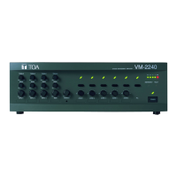
17
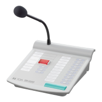
1. Indication Label Holder
Write the name, purpose, etc. of the indicator and key
on a label and insert the label into the holder from the
top. Labels can be printed using the setting software.
(For more information, refer to "Printing Remote
Microphone Labels" in the separate software manual.)
2. Power Indicator (green)
Lights when power is supplied to the unit.
3. Communication Failure Indicator (yellow)
Flashes when a failure is detected in
communications with the VM-3240VA.
4. Not used.
Lights when the system is in emergency status.
5.
Broadcast Zone / Automatic general broadcast
Announcement Start Indicators (green)
Indicator’s function assigned to each indicator is
determined by software settings.
Broadcast Zone Indicators
Light when their corresponding zones are selected.
Automatic general broadcast Announcement
Start Indicators
Light when an automatic announcement is
started.
6. Broadcast Zone Selector / Automatic general
broadcast Announcement Start Keys
Key function assigned to each key is determined
by software settings.
Broadcast Zone Selector Keys
Select broadcast zones. Pressing the Talk key (7) after
zone selection allows microphone announcements to
be broadcast over the selected zone(s).
Automatic general broadcast Announcement Start Key
Automatic general broadcast announcements
are broadcast over the selected zone(s).
7. Talk Key
This key is used for general broadcast microphone
announcements. Pressing the Talk key after zone
selection allows microphone announcements to be
broadcast over the selected zone(s).
8. Talk Indicator (green)
Lights when the Talk key (7) is pressed.
9.
External Microphone In-Use Indicator (orange / green)
Flashes when a paging call is made from the
external remote microphone.
Orange: Indicates the mode that disables
broadcasts from the unit.
Green: Indicates the mode that allows the unit to
interrupt broadcasts from external equipment.
10. Not used.
11. Microphone
Used for making announcements.
12. DIP Switch
Used to set the unit ID number and equipment
functions. (Refer to "DIP Switch Functions" on
page 70.)
Switches 1 and 2
Set the ID number of the Remote Microphone.
Default setting: ON
(Refer to "Unit ID Number Settings" on page 70.)
Switch 3
Not used.
Default setting: ON
Switch 4
Sets the Talk key’s operating system.
Default setting: ON
(Refer to "Talk Key Settings" on page 70.)
Switch 5
Not used.
Default setting: ON
Switch 6 [COMPRESSION]
Enables/disables compression.
Default setting: ON
(Refer to "Compression Settings" on page 70.)
13. RM-210 Connector [Extension]
Not used.
14. Power Supply Input Connector
The VM-3240VA or VM-3240E can supply power
to one RM-200M Remote Microphone. Connect
a power supply to this connector.
15. Link Connector (RJ45 Connector)
Connects to the VM-3240VA’s or other RM-
200M’s LINK connector.
16. Not used.
17. Microphone Volume Control
Adjusts the volume of the unit’s microphone (11).
Rotate clockwise to increase the microphone volume.
Rotate counterclockwise to decrease the
microphone volume.
18.
External Microphone Input Jack (3.5 mm mini jack)
An electret condenser microphone can be connected
to this terminal. Connecting a microphone to this jack
disables the unit’s microphone (11).