Page 2-2 Document Ref 942583-001 Rev 8
Site Preparation Quantium 510 Installation Manual
2 SITE PREPARATION
2.1 General
Tokheim dispensers must only be installed on a level island or forecourt surface.
The ground plan will depend on the model ordered. See drawings in Section 3.
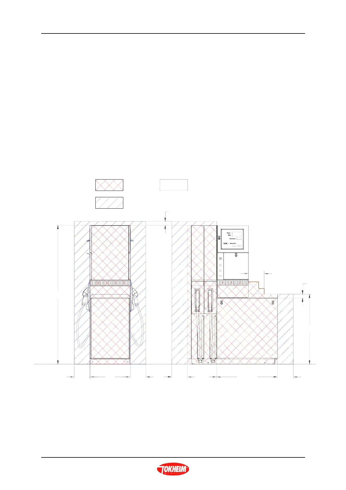
2.1.1 ZONING DIAGRAMS
The classification of vapour barriers is indicated in the following diagram.
The zone classifications shown are always the highest applicable to that location
within the dispenser.
Q510 DISPENSER - STANDARD HEAD CONFIGURATION
Island Level
1781
Zone 1
Non-hazardous zone
Zone 2
Dim B
Dim A
900
50
200
50
200
200
200
200
520
Hydraulic
housing
Zone 1
Zone 1
Zone
2
Zone
2
Zone
2
Zone
2
Hose
cassette
housing
Note:- On this drawing all Zone 2 areas are external of the dispenser.
Zone 1 areas are internal in the dispenser.
Dimensions A and B will depend on dispenser model/number of hoses - refer to Section 3