Specifications
GRS-1 Operator’s Manual
A-8
Connector Specifications
The GRS-1 has one antenna connector for radio transmission/
reception and three port connectors for power and data upload/
download.
Serial Connector
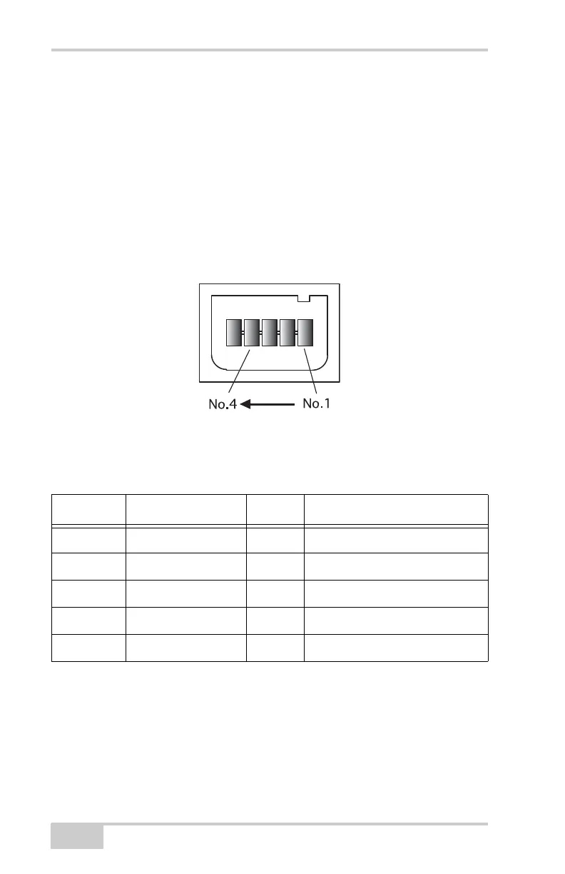
The serial connector (Figure A-1) is a sealed receptacle, 5 pin, port.
This connector is configured as port A of the internal GPS receiver.
Figure A-1. Serial RS232 Connector
Table A-4 gives the serial port’s pin specifications.
Table A-4. Serial Pin Specifications
Number Signal Name Dir Details
1 TXD O Clear to send
2 RXD I Request to send
3 GND - Signal ground
4 GND - Signal ground
5 - - Not used