A USB compliant design needs to detect over-current on the provided bus power output. The
output rail needs to be turned off in case an over-current condition occurs. The USB_1_OC# signal
is used to notify the module that an over-current condition has occurred. This signal is active-low
and requires a pull-up resistor to 1.8V on the baseboard.
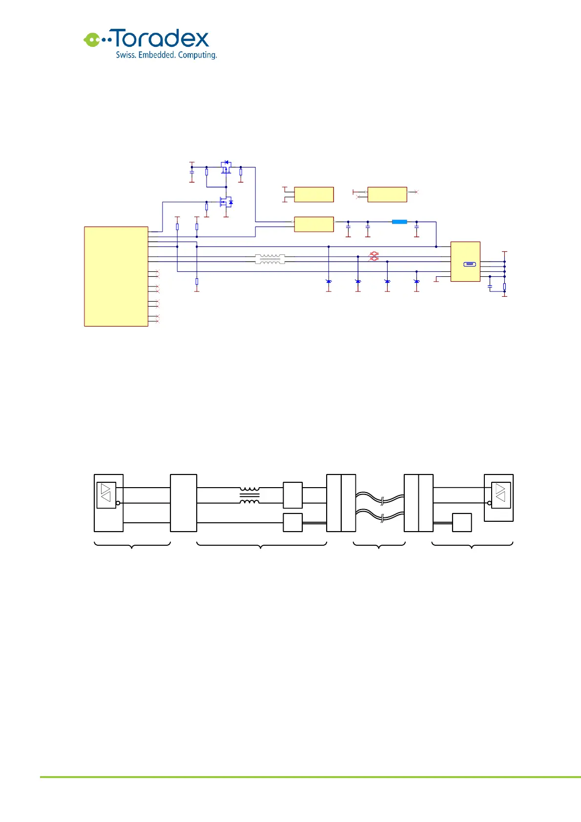
Figure 17: USB OTG reference schematic
2.4.2.2 USB-C Dual Role Schematic Example
The term USB OTG is only used in conjunction with the USB Micro-AB or the obsolete USB Mini-AB
receptacle. When it comes to USB Type-C receptacles and connectors, the term OTG is replaced
with the name Dual Role Device (DRD). Like the old USB OTG, a USB-C DRD can change its role
from being a device to be a host and vice versa. The USB OTG receptacle was using the ID pin for
detecting whether a Type-A or Type-B plug is connected in order to know in which role the
communication must start and whether the bus power needs to be provided or not. The USB Type-
C does not feature an ID pin anymore. The detection of the role is done by the two Configuration
Channel (CC) pins.
Figure 18: USB Type-C Block Diagram
The CC pins serve multiple purposes on a Type-C connector. It is used for detecting the orientation
of the connector in the receptacle, negotiating the power delivery (voltage and current), and
negotiating the role of the device. For the CC detection of a DRD port, a port control IC is used.
The TUSB321 can translate the CC detection to a USB OTG ID signal which can be used with the
Verdin module. If the port has negotiated being source for the power (Downstream Facing Port
DFP), the VBUS need to be provided. The TUSB321 can be strapped to announce different current
levels to the device. The over current protection IC on the carrier board needs to be set to a level
that complies with announced current.
The USB 2.0 signals are in the center of the USB Type-C connector. Therefore, the signals of the
top and bottom side of the connector can be connected together without significant stubs. This
means no multiplexer is required if the SuperSpeed signals are not provided to the connector.