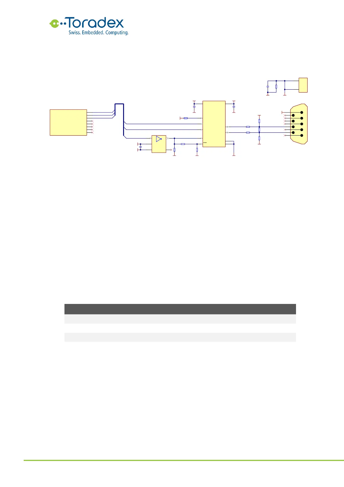
Like the RS422, the RS485 specification does not describe a standard connector. The reference
schematic shown below uses a DE-9 connector which may have a different pin-out compared to
some peripheral devices.
Figure 41: RS485 Reference Schematic
2.10.3 Unused UART Signal Termination
Unused UART interface signals can be left unconnected. For debugging purpose, it is
recommended to have at least the UART_3_RXD and UART_3_TXD signals accessible.
2.11 SPI
The serial peripheral interface (SPI) bus is a synchronous, full duplex interface. The Verdin module
form factor features one SPI interface in the "Always Compatible" class. The interface has one chip
select signal. Some modules may feature an additional chip select signal or additional SPI
interfaces as secondary function of other pins.
The clock polarity and phase of the SPI bus is not standardized. Some peripherals latch the data at
the positive edge of the clock while others latch it at the negative edge. The SPI modes describe
these different behaviors. Make sure that the relevant Verdin module and the peripheral devices
are set to the same SPI mode.
Assemble R61 and remove 59:
not get an echo of the sent message)
ECHO disabled (the sender does
1
2
3
4
5
6
7
8
9
A-DS 09 A/KG-T4S
X16A
R55
120R
SN65HVD01DRCR
RE
4
VL
1
R
2
D
5
DE
3
GND
6
SLR
7
A
8
B
9
VCC
10
GND-PAD
11
IC6
100nF
16V
C71
GND
100nF
16V
C79
GND
+V3.3_SW+V1.8_SW
S1
S2
SHIELD
A-DS 09 A/KG -T4S
X16B
GND
1nF
2KV
C52
GND_CHASSIS
GND
SN74LVC1G04DCKR
NC
1
A
2
GND
3
Y
4
VCC
5
IC8
GND
RS485_A
RS485_B
RS485_CON_A
RS485_CON_B
GND
RS485_DE
RS485_RE#
100nF
16V
C80
+V1.8_SW
GND
680R
R58
680R
R53
+V3.3_SW
GND
NA
NA
R60
10K
R61
10K
1M
R45
R54 10R
R56 10R
UART_1_RXD
UART_1_TXD
UART_1_RTS
GNDUART_1_RXD
129
UART_1_TXD
131
UART_1_RTS
133
UART_1_CTS
135
UART_2_RXD
137
UART_2_TXD
139
UART_2_RTS
141
UART_2_CTS
143
X1F
2309409-2
UART_1_TXD
UART_1_RTS
UART_1_RXD
0R
R59
NA
0R
R52
+V1.8_SW
NA
SLR floating: 20Mbps
SLR high: 250kbps