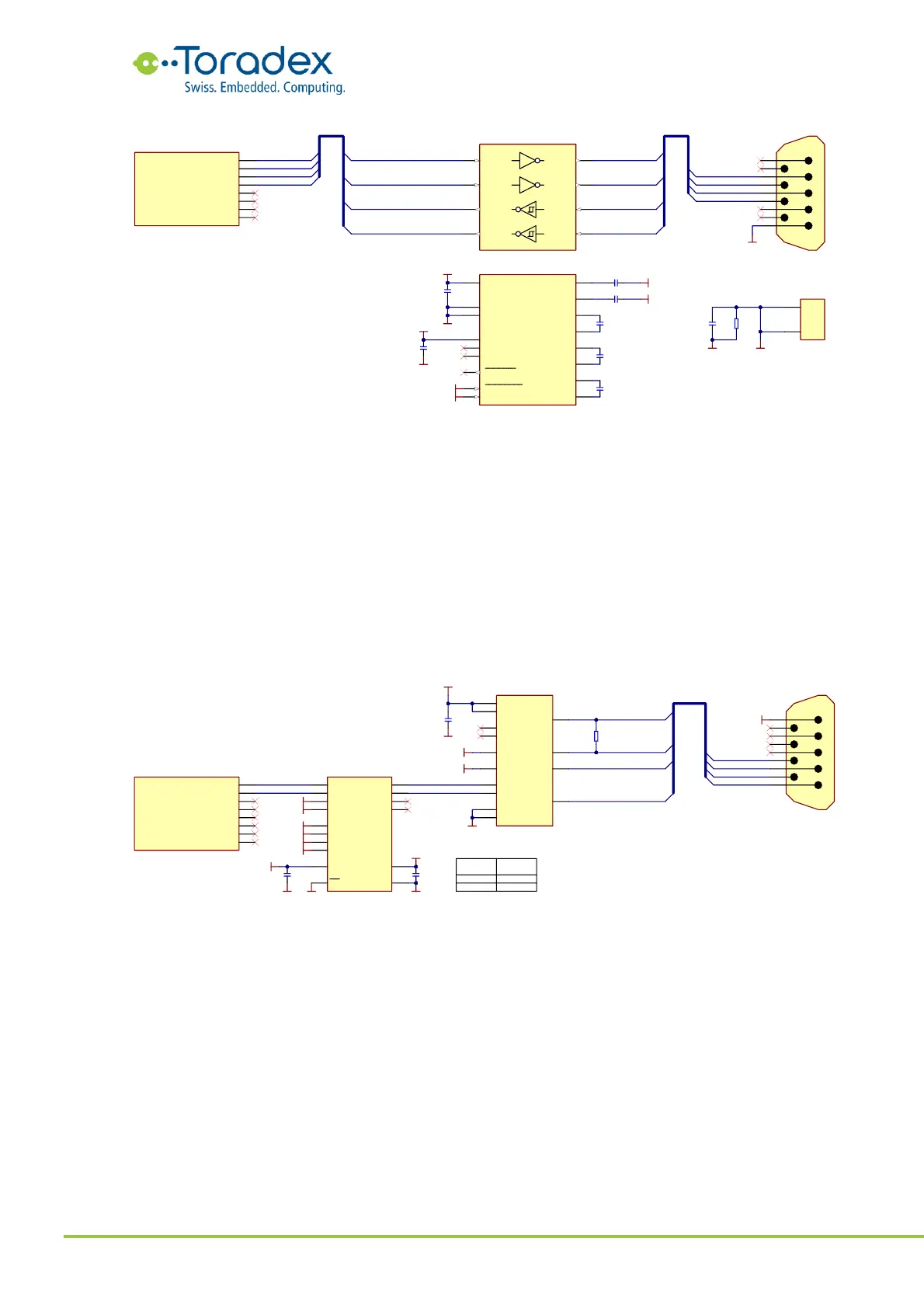
Figure 39: RS232 Reference Schematic
2.10.2.2 RS422 Reference Schematics
The RS422 is a full-duplex serial interface with differential pair signals. This allows higher data
rates over longer distances as with the RS232. Since the RS422 has separate RX and TX signal
pairs, no additional control signals are required for changing the signal direction. This means, the
RS422 requires only the RX and TX signals of the UART interface. Therefore, it is possible to use any
of the four standard UART interfaces of the Verdin standard.
The RS422 specification does not contain a connector. Therefore, there is no standard connector
for this interface available. The reference schematic below uses the 9-pin D-sub connector (DE-9).
Peripherals might have a different pin-out even if they use a DE-9 connector as well.
Figure 40: RS422 Reference Schematic
2.10.2.3 RS485 Reference Schematics
The RS485 interface is a half-duplex serial interface with differential pair signals. Instead of two
differential pair wires (RS422), only one pair is used for transmitting and receiving the data. The
bus allows Multi-Point connections. Since the transceiver needs to be set either in the transmitting
or receiving mode, an additional control signal is required. It is recommended to use the RTS signal
of the corresponding UART interface. The RTS signal is only available on the UART_1 and UART_2
as Verdin standard interface. The schematic shown below inverts the RTS signal for the data enable
input of the transceiver. Some modules allow inverting the signal in software, but it is
recommended to keep the inverter circuit in in the RTS signal to maintain compatibility with
different modules and drivers provided by Toradex. For some applications, it is desirable that the
UART controller does not see the TX message on its RX pins (echo of the sent message). In this
case, the receive enable pin (RE#) can be driven as well with the RTS signal. This turns off the RX
output buffer during sending a message.