3.4 Power Supply Use Cases
The power control pins of the Verdin module are very flexible and allow different use cases for the
power supply on the carrier board. The following approaches are just examples for the most
common use cases. There are other options possible.
3.4.1 Switched VCC Approach (Verdin Development Board)
The switched VCC approach is basically the one which is implemented on the Verdin Development
Board. There is a power button control IC which handles the switching of the main VCC for the
module. This approach makes use of the CTRL_FORCE_OFF_MOCI# signal which switches off VCC
after the module has been successfully shutdown.
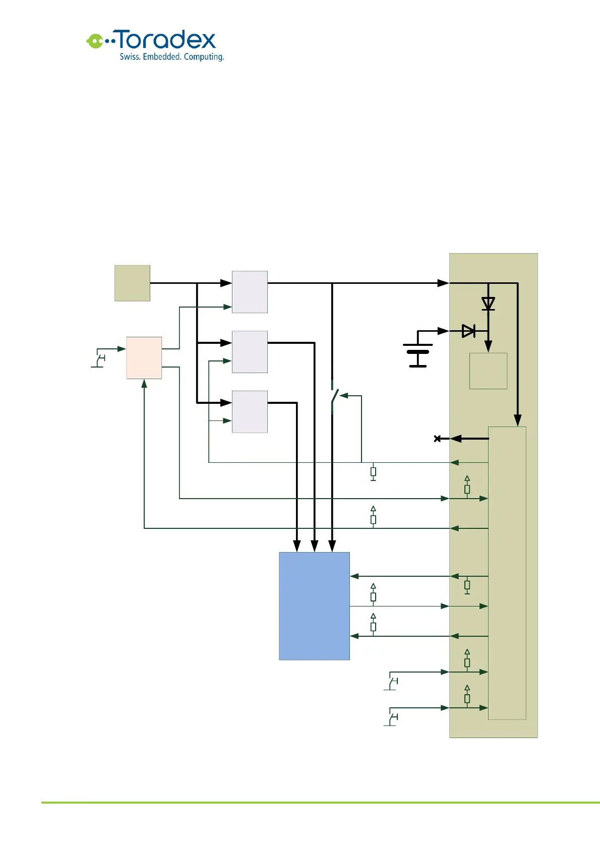
3.4.1.1 Power Block Diagram
Figure 57: Switched VCC Approach Block Diagram
The module gets powered from a 5V buck regulator. This regulator is enabled by a button control
IC. Short pressing the power button will enable the 5V buck regulator which powers up the Verdin