4.4 Module Dimensions
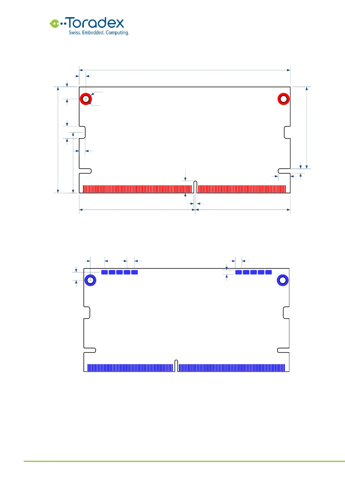
Figure 90: Module dimensions top side (mm)
On the bottom side of the Verdin module, there are 10 test pads (5 on each side). These pads are
used by the module manufacturer for test purposes. On a customer carrier board, these test pads
do not need to be connected.
Figure 91: Module dimension bottom side (mm)
4.5 Connector and Standoff Land Pattern Requirements
The required land pattern depends on the need for additional standoffs. The standoffs are
optional. Either no standoffs, only the two at the edge of the module or all four (including the ones
on the side of the connector) are acceptable. The land pattern below is optimized for the TE
Connectivity 2309409-2 SODIMM DDR4 connector. If a different connector is used, please check
the land pattern recommendations of the connector manufacturer.