2.14 PWM
The Verdin module form factor defines three pulse width modulator (PWM) outputs. PWM_1 is a
general purpose PWM and is in the "Always Compatible" class. The PWM_2 is also intended to be
used for general purpose applications, but it is in the "Reserved" class. The third signal PWM_3_DSI
is dedicated for the display back light control of the MIPI DSI port. This signal is also labeled as
"Reserved". Some Verdin modules feature more than three PWM outputs. These signals are
available as alternate functions of other interfaces or in the "Module-specific" section of the module
edge connector. The additional PWM outputs are not guaranteed to be pin compatible with other
Verdin modules.
The maximum output frequency and the possible duty cycle steps vary between the different Verdin
modules. Please carefully read the datasheets of Verdin modules for more information on the
performance of the PWM interface pins.
2.14.1 PWM Signals
Table 29: PWM Signals
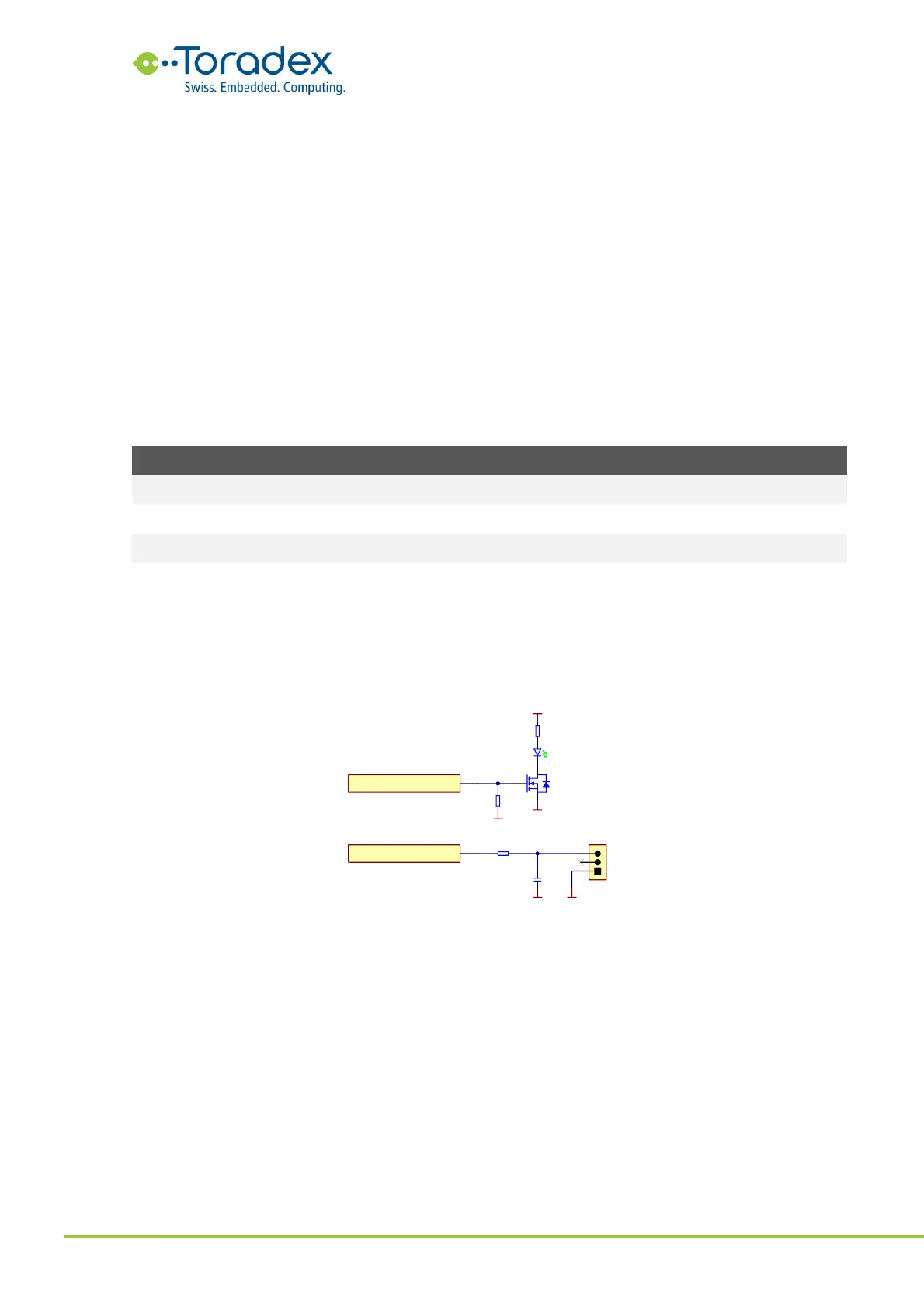
2.14.2 Reference Schematics
The PWM output signals can be used to drive motors, LEDs, robotic servos, fans, etc. It is possible
to get an analog signal with a simple low pass filter.
Figure 43: PWM Example Schematic
2.14.3 Unused PWM Signal Termination
Unused PWM signals can be left unconnected.