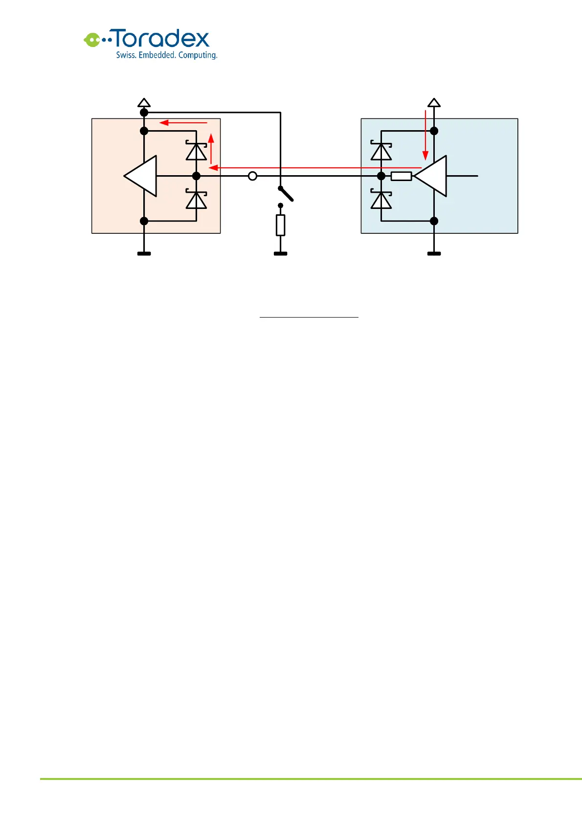
Figure 72: Evaluating the total internal resistance of the backfeeding
Using the numbers in Figure 72 as an example, we get the following total internal resistance:
The total internal resistance measured on the IO rail can then be compared to the estimated
internal resistance of the backfeeding IO pins. If the total resistance is smaller than the combined
resistance of the IO pins, there are still other backfeeding sources to be uncovered.
Comparing the results from Figure 71 and Figure 72, we see that the total internal resistance is
about three times smaller than a single signal pin. This means there are probably a total of three
(similar) signal pins that are backfeeding to this IO rail.
3.5.5 Backfeeding Prevention
There are multiple approaches for preventing backfeeding from happening. Some of them are very
cost-effective but are not applicable to all types of signals or situations. Other solutions are
expensive or require extra precious PCB real estate. Therefore, defining the right backfeeding
prevention approach is difficult. The following list of potential solutions starts from the cheap and
straightforward approaches and stretches to the complicated and expensive ones. This is not a
complete list. There are other solutions that are not discussed here. Some backfeeding
countermeasures are specific to an interface. Therefore, following the reference schematics is
advised.