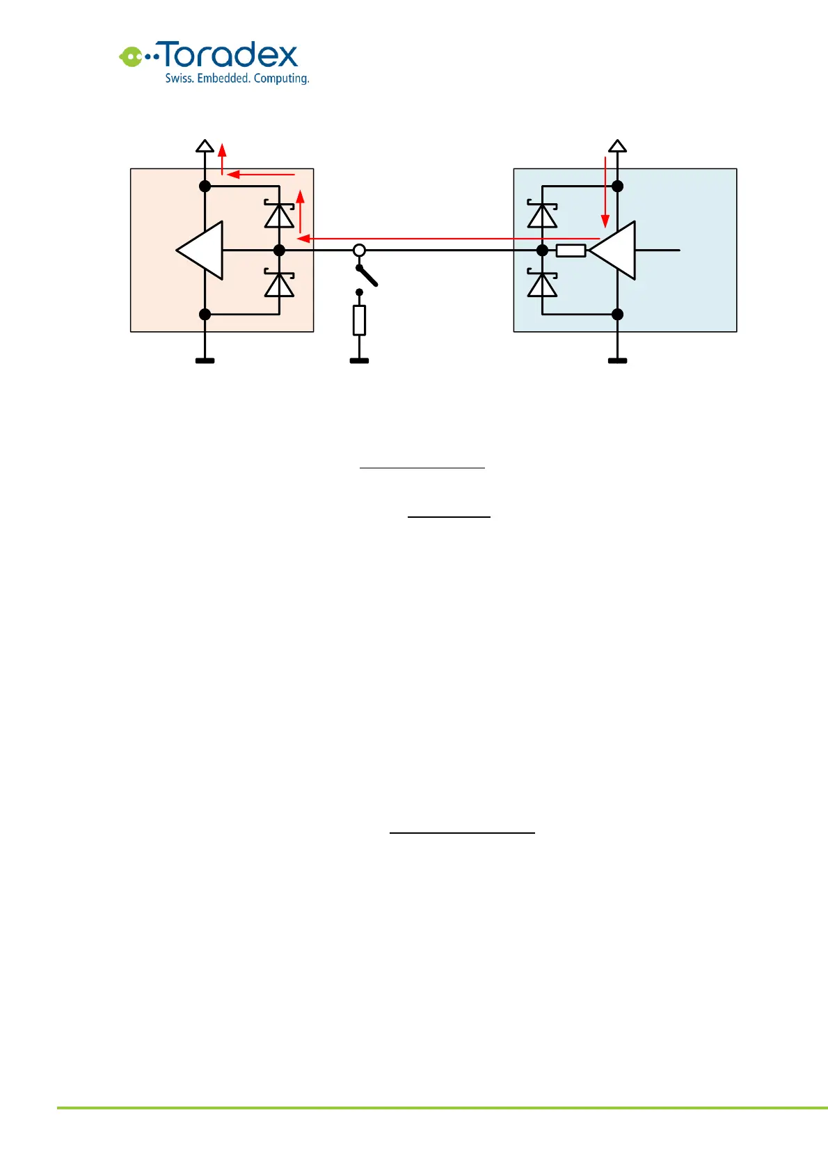
Figure 71: Evaluating the internal resistance of the driver
With the help of these formulas, the measured values in Figure 71 would lead to the following
internal resistance and backfeeding current:
Often it is crucial to know whether all the backfeeding pins are identified or the search for
backfeeding sources must continue. Ideally, you might be able to disconnect individual pins by
removing series resistors or a jumper (for example, possible on the Verdin Development Board).
Unfortunately, this is not always the case. However, there is another method for estimating the
number of backfeeding pins.
By adding a load resistor to the IO rail and observing the residual voltage changes, the total
internal resistance of the backfeeding can be estimated. A good value for the load resistor is 100Ω.
You might need to select a different value if the voltage is dropping to little or too much. The best
values can often be achieved by a voltage drop between 50mV and 100mV. The formula for
estimating the internal resistance is the same as used for the individual pin. Assuming the voltage
drop over the ESD diode is constant, the diode voltage drop is eliminated from the formula. Please
keep in mind that this formula only provides a rough estimated value. There might be devices on
the IO rail which behave non-linear to voltage changes. Therefore, the forced voltage change
should be kept small for better results.