2.4.2.4 USB 3.x Host Connector Schematic Example
The USB_2 port of the Verdin module specifications reserves additional SuperSpeed signals which
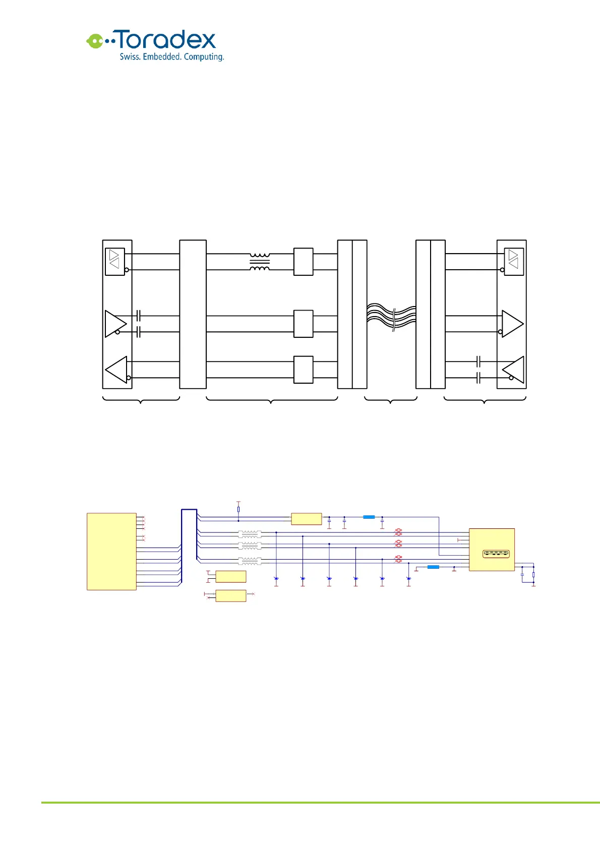
makes it possible to provide a USB 3.x host interface. The SuperSpeed signals are physically
related to the PCIe interface. Therefore, special attention is required with the series capacitors. The
AC coupling capacitors of the TX SuperSpeed signals are located on the Verdin module while the
capacitors for the RX signals are located on the USB device. Therefore, no additional capacitors are
required nor permitted on the carrier board. The USB 2.0 data signals do not need any series
capacitors at all.
If the USB signals are externally available, ESD protection diodes need to be placed on all the USB
signals. Make sure that the protection diodes are compliant with the very high frequency of USB
3.x.
Figure 22: USB 3.x host block diagram
Please note that a Type A USB 3.x compliant host port needs to provide up to 900mA bus supply
while the USB 2.0 ports where only rated up to 500mA for a regular, non-charging port. Make
sure the bus voltage power distributor switch IC can deliver this higher current. According to the
USB specifications, a output capacitor of at least 100µF need to be added to the USB bus voltage.
Figure 23: USB 3.0 host reference schematic
2.4.2.5 USB 3.x Device Down Schematic Example
Device-Down means that the USB device is soldered to the carrier board. The AC coupling
capacitors for the SuperSpeed RX lane (TX from the device) need to be placed on the carrier board.
As the capacitors for the TX lane are located on the Verdin module, no additional capacitors are
required nor permitted on the TX lines.
ESD protection diodes and common mode chokes are usually not needed for device-down
implementations.