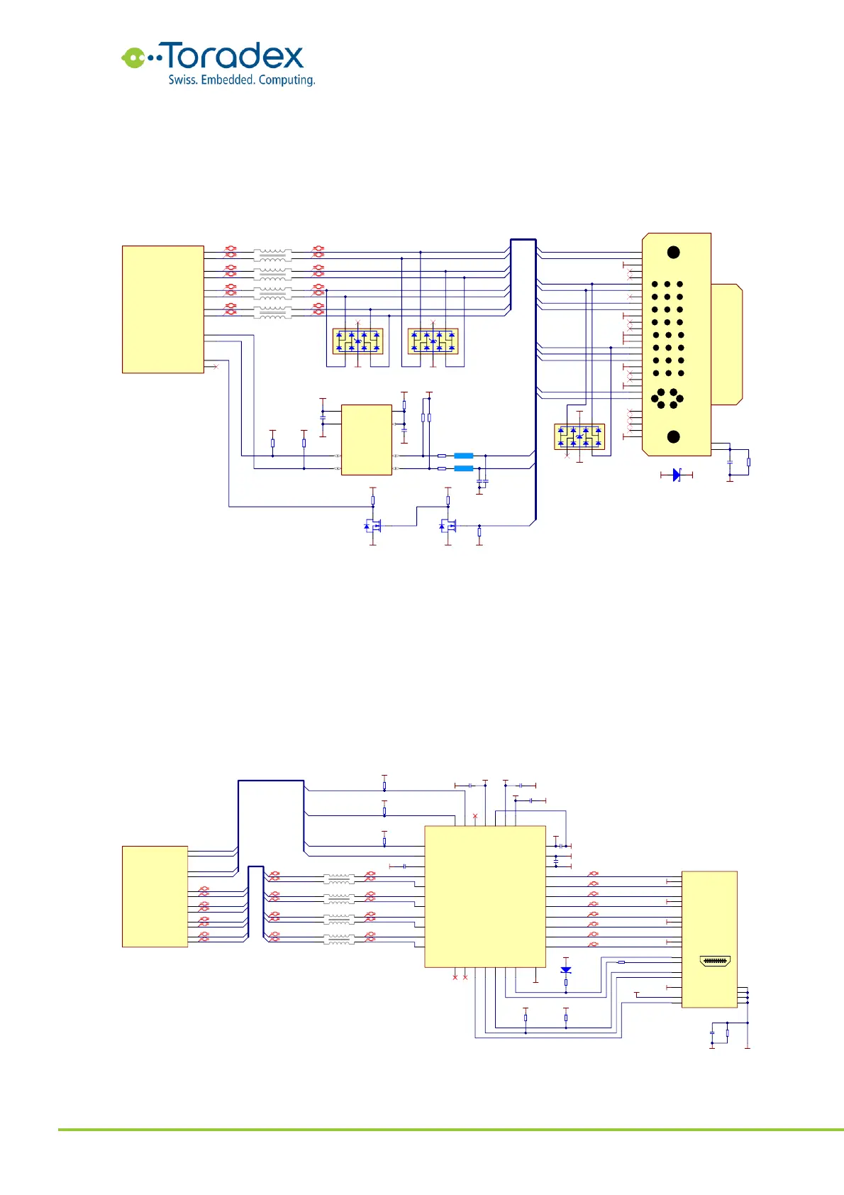
The following schematic example shows a DVI-D implementation, since the Verdin module does
not provide an VGA output. The DDC signals require a level shifter since the signal level on the
Verdin module is 1.8V while the DVI uses 5V. The same is necessary for the hot plug detect signal.
The TDMS signals need to be ESD protected using diodes. The schematic example shows a discrete
solution for the level shifting and protection. There are integrated solutions also available.
Figure 28: DVI-D reference schematic
2.5.2.2 HDMI Schematic Example
The HDMI connector does not feature an Analog VGA interface, but there is an optional Consumer
Electronics Control (CEC) interface available. This one-wire interface is used to control consumer
audio and video devices such as televisions or AV receivers. There are many different trade names
for CEC (VIERA Link, Anynet+, EasyLink, Aquos Link, BRAVIA Link, etc.) The CEC is a 3.3V interface
on the HDMI connector. Therefore, a level shifter is required.
The I
2
C signals for the DDC and the hot-plug detection (HPD) need to be shifted to/from the 5V
logic level of the HDMI interface to the Verdin module signal level of 1.8V. The DDC requires
external pull-up resistors on the carrier board.
Figure 29: HDMI reference schematic