software and ramping down power rails on the module (including the PWR_1V8_MOCI). In this off-
state, the system can be turned on by pressing again the power button. A long pressing on the
power button (>5s) initiates an emergency power shutdown. All power rails will be turned off. The
module can be turned back on by using the power button. Without the power button, the module
can only be turned on after shutting it down in software and power cycling the main VCC rail after.
All the rest of the rest of the power management signals can be left unconnected.
3.4.2.2 System Power States
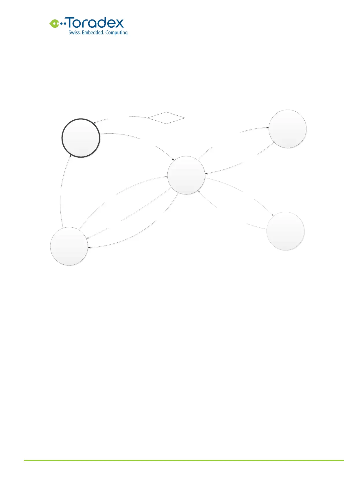
Figure 61: System Power States and Transitions
The sleep state is optional. Therefore, this state and its transitions are grayed out in the state
diagram. If the reset button (CTRL_RESET_MICO#) is not implemented in such a power scheme, it
is still possible to do software initiated reset cycles. Without implementing a power button
(CTRL_PWR_BTN_MICO#), the only option for exiting the module OFF state is to “unplug” the
system.
3.4.2.3 Reference Schematics
The reference schematics below show the minimum amount of external components that are
required for running the Verdin module.