3.4.3.1 Power Block Diagram
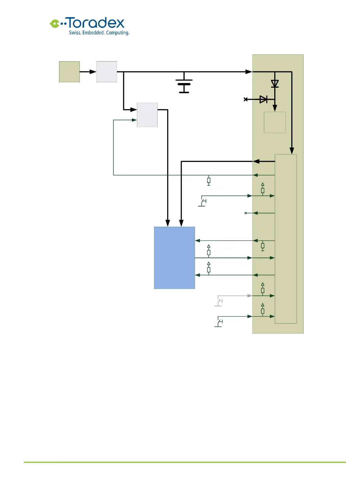
Figure 63: Switched VCC Approach Block Diagram
The module VCC can be connected directly to the system voltage which is coming from the battery
charger IC and is also used for charging the Li-ion battery. Having the module VCC connected
directly to the system battery means that VCC will be available to the module all the time and a
the VCC_BACKUP rail is not required to be provided to the module.
The system voltage can range from 3.135V to 4.4V which makes the creation of a 3.3V +/-5% rail
challenging. A better approach is to run peripherals from 1.8V and reducing the components on
3.3V. Some interfaces like the SD card require a 3.3V rail. Since the SD card can officially run
down to 2.7V, a suitable option could be using an LDO regulator with a very low dropout or a
buck converter with constant-on option.