2.Positionthecastorwheelaxlesinthesameholesin
allcastorforks.Refertothechart(Figure22)to
determinethecorrectholesforthesetting.
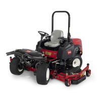
Figure22
1.Castorarmheightofcut
mountingholes
3.Castorforkheightofcut
spacers
2.Castorforkheightofcut
mountingholes
Note:Whenoperatingat2-1/2inch(64mm)
heightofcutorhigher,theaxleboltshouldbe
installedinthebottomcastorforkholetoprevent
grassbuildupbetweenthewheelandthefork.
Whenoperatingatheightsofcutlowerthan2-1/2
inches(64mm)andgrassbuildupisdetected,
reversethemachinesdirectiontopullanyclippings
awayfromthewheel/forkarea.
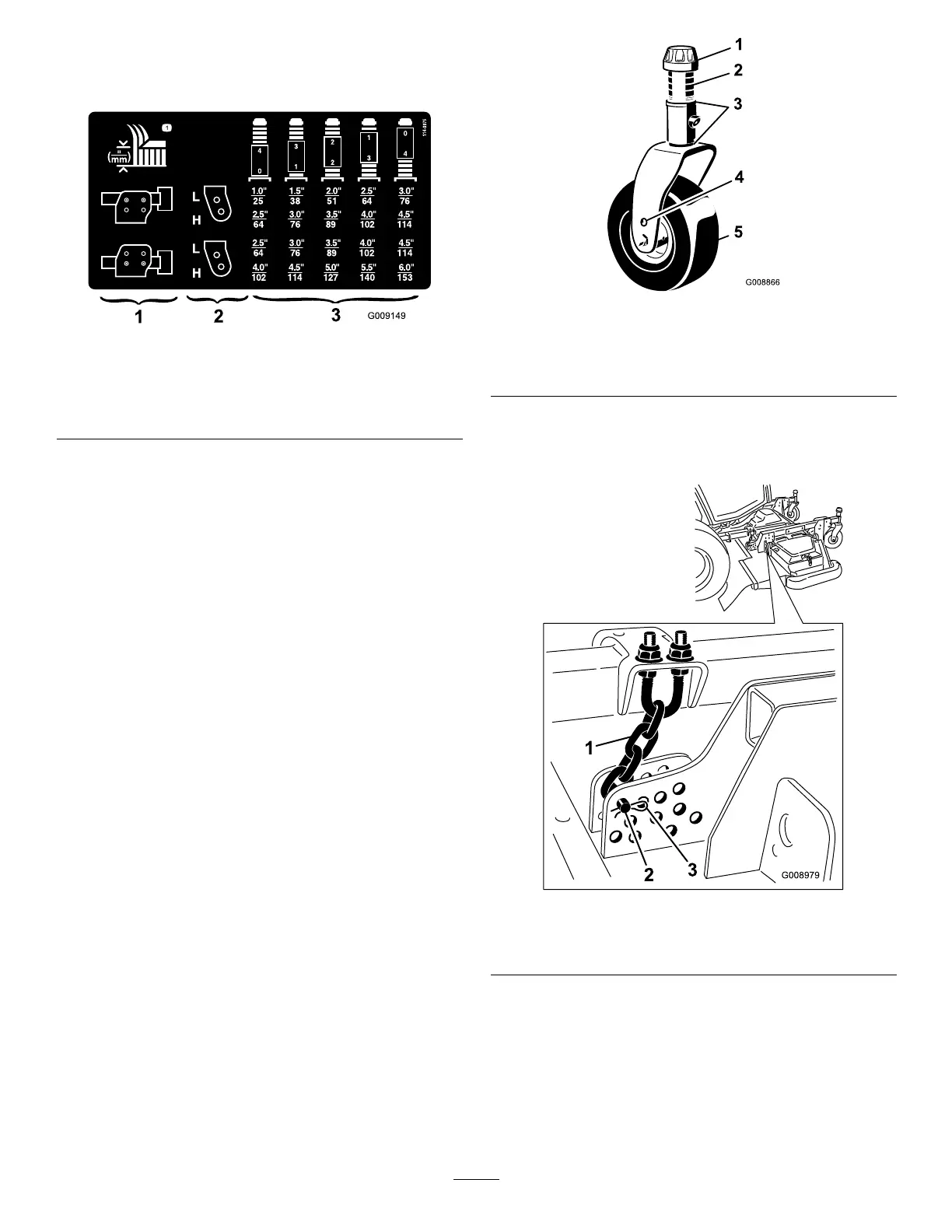
3.Removethetensioningcapfromthecastorshaft
(
Figure23).andslidetheshaftoutofthecastor
arm.Put2shims(1/8inch[3mm])ontothecastor
shaftasoriginallyinstalled.Slidetheappropriate
numberof1/2inchspacersontotheshafttoget
thedesiredheight-of-cut.
Note:Theshimwashersmaybeusedinany
combinationaboveorbelowthecastorarmhub
asrequiredtoachievethedesiredheightofcutor
decklevel.
Refertothechart(
Figure22)todeterminethe
combinationsofspacersforthesetting:
4.Pushthecastorshaftthroughthefrontcastor
arm.Installtheshims(asoriginallyinstalled)and
theremainingspacersontotheshaft.Installthe
tensioningcaptosecuretheassembly(Figure23).
Figure23
1.Tensioningcap4.Topaxlemountinghole
2.Spacers(4)5.Castorwheel
3.Shims(2top&2bottom
5.Removethehairpincotterandclevispinsecuring
theheight-of-cutchainstotherearofthecutting
unit(Figure24).
Figure24
1.Height-of-cutchain
3.Hairpincotter
2.Clevispin
30