spacersontotheshaft.Installthetensioningcap
tosecuretheassembly.
AdjustingtheSkids
Theskidsshouldbemountedinthelowerposition
whenoperatingatheightsofcutgreaterthan2-1/2
inches(64mm)andinthehigherpositionwhen
operatingatheightsofcutlowerthan2-1/2inches(64
mm).
Note:Whentheskidsbecomeworn,youcanswitch
theskidtotheoppositesidesofthemower,ipping
themover.Thiswillallowyoutousetheskidslonger
beforereplacingthem.
1.Loosenthescrewatthefrontofeachskid
(Figure29).
Figure29
1.Skid
2.Removetheange-headboltsandnutsfromeach
skid(Figure29).
3.Moveeachskidtothedesiredpositionandsecure
themwiththeange-headboltsandnuts.
Note:Onlyusethetoporcentersetsofholesto
adjusttheskids.Thebottomholesareusedwhen
switchingsidesatwhichtimetheybecomethetop
holesontheothersideofthemower.
4.Torquethescrewatthefrontofeachskidto80to
100in-lb(9to11N⋅m).
AdjustingtheCuttingUnit
Anti-ScalpRollers
Thecuttingunitgagewheelsandrollershouldbe
mountedinthelowerpositionwhenoperatingat
heightsofcutgreaterthan2-1/2inches(64mm)and
inthehigherpositionwhenoperatingatheightsofcut
lowerthan2-1/2inches(64mm).
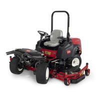
AdjustingtheRoller
1.Removethescrewandnutsecuringtherollershaft
tothedeckbracket(Figure30).
Figure30
1.Gagewheel2.Screwandnut
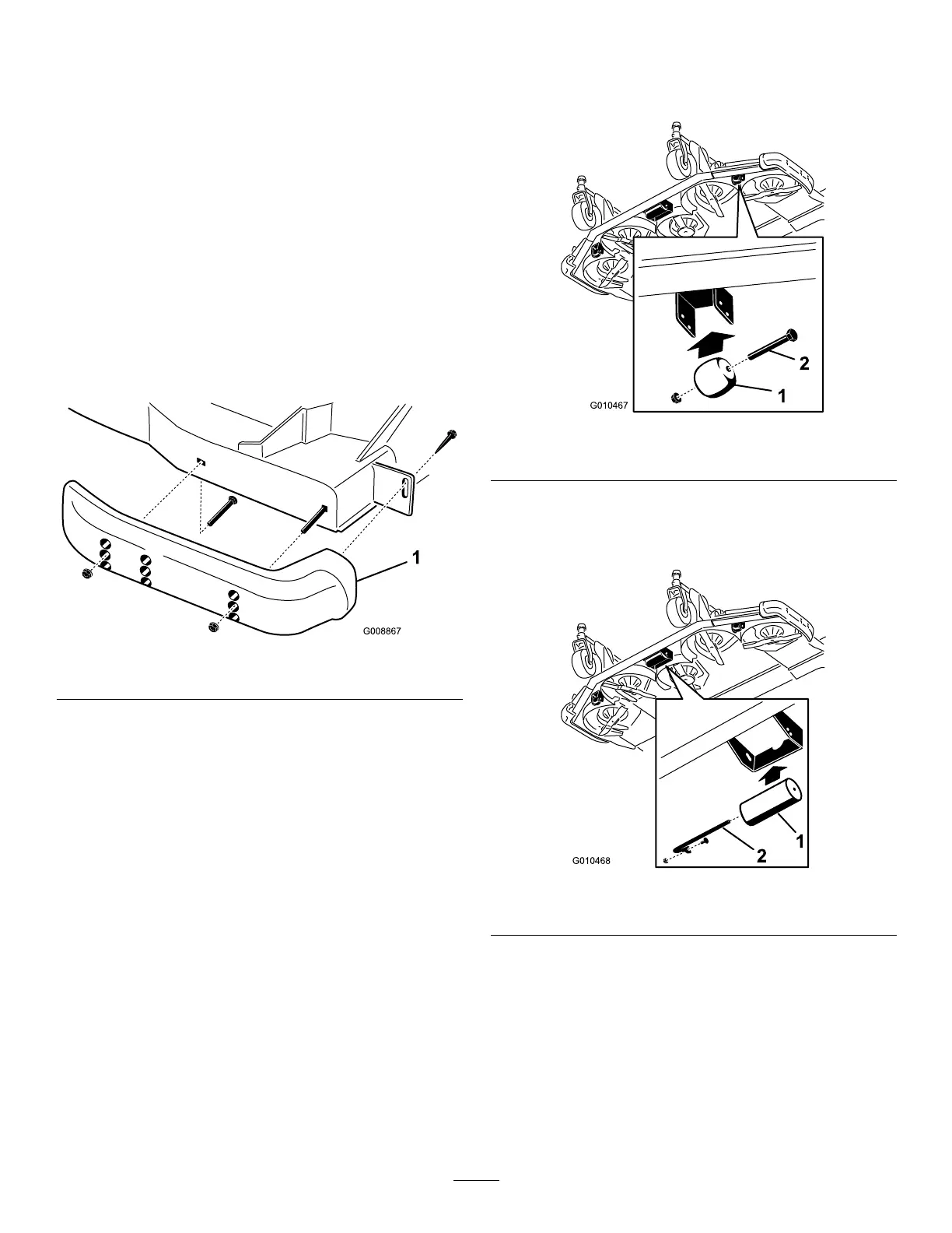
2.Slidetheshaftoutofthelowerbracketholes,align
therollerwiththetopholes,andinstalltheshaft
(
Figure31).
Figure31
1.Roller
2.Rollershaft,screwandnut
3.Installthescrewandnuttosecuretheassemblies.
AdjustingtheGageWheels
1.Removetheboltandnutsecuringthegagewheelto
thecuttingunitbrackets(Figure30).
2.Aligntherollerandspacerwiththetopholesinthe
bracketsandsecurethemwiththeboltandnut.
32