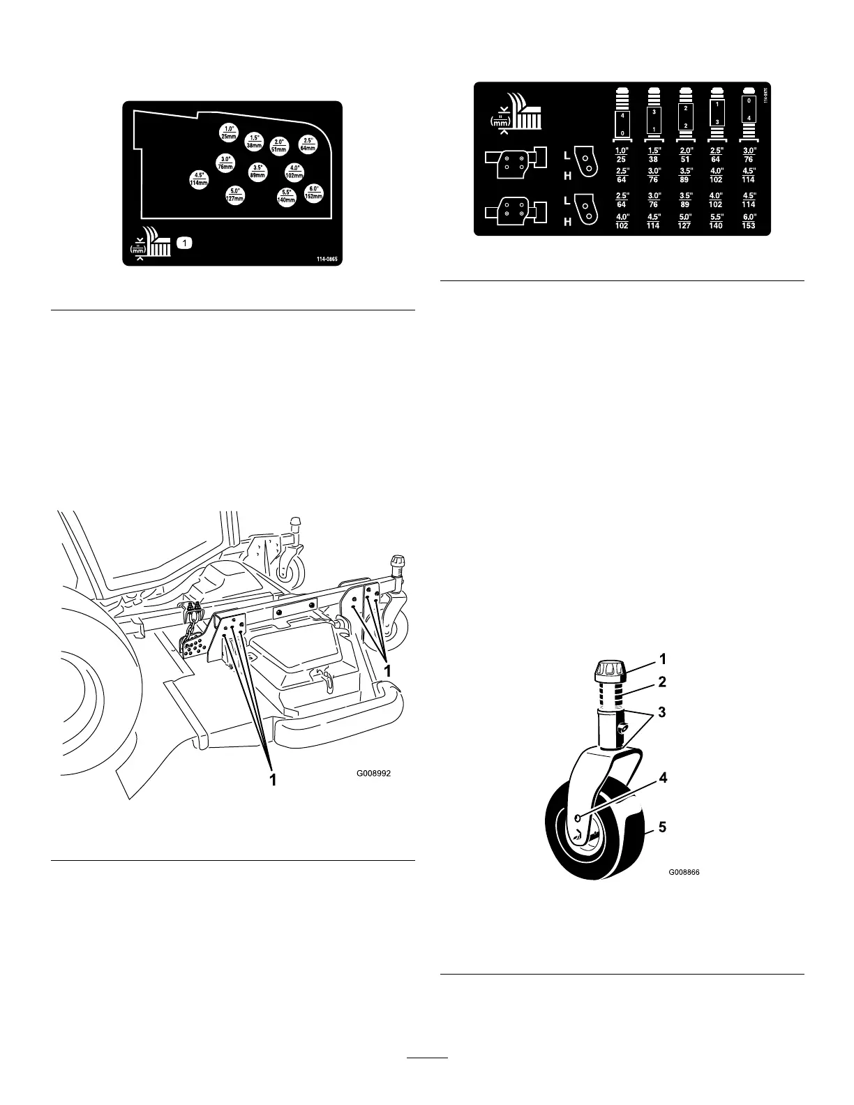
6.Mounttheheight-of-cutchainstothedesired
height-of-cuthole(Figure25)withtheclevispin
andhairpincotter.
Figure25
Note:Whenmowingatheight-of-cutsbelow
2–1/2inches(51mm),movetheskids,gagewheels
androllerstothehighestholes.
7.Toattainthe5to6inch(102to153mm)heightof
cutsettings,removethemountingboltssecuring
thedeckhangerbracketstotheheightofcutcastor
armsandremountthedeckhangerbracketstothe
heightofcutcastorarmsusingthelowersetof
holes(
Figure26).
Figure26
1.Lowermountingbolts
SideCuttingUnits
1.Starttheengineandraisethecuttingunitssothat
theheight-of-cutcanbechanged.Stoptheengine
andremovethekeyafterthecuttingunitisraised.
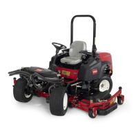
2.Positionthecastorwheelaxlesinthesameholes
inallcastorforks.Refertothechart(Figure27)
todeterminethecorrectholesfortheheightof
cutsetting.
Figure27
Note:Whenoperatingat2-1/2inch(64mm)
heightofcutorhigher,theaxleboltshouldbe
installedinthebottomcastorforkholetoprevent
grassbuildupbetweenthewheelandthefork.
Whenoperatingatheightsofcutlowerthan2-1/2
inches(64mm)andgrassbuildupisdetected,
reversethemachinesdirectiontopullanyclippings
awayfromthewheel/forkarea.
3.Removethetensioningcapfromthecastorspindle
shaft(
Figure28)andslidethecastorshaftoutof
thecastorarm.Put2shims(1/8inch[3mm])onto
theshaftasoriginallyinstalled.Slidetheappropriate
numberof1/2inchspacersontotheshafttoget
thedesiredheight-of-cut.
Note:Theshimwashersmaybeusedinany
combinationaboveorbelowthecastorarmhub
asrequiredtoachievethedesiredheightofcutor
decklevel.
Figure28
1.Tensioningcap4.Topaxlemountinghole
2.Spacers(4)5.Castorwheel
3.Shims(2topand2bottom)
4.Pushthecastorshaftthroughthecastorarm.Install
theshims(asoriginallyinstalled)andtheremaining
31