g473684
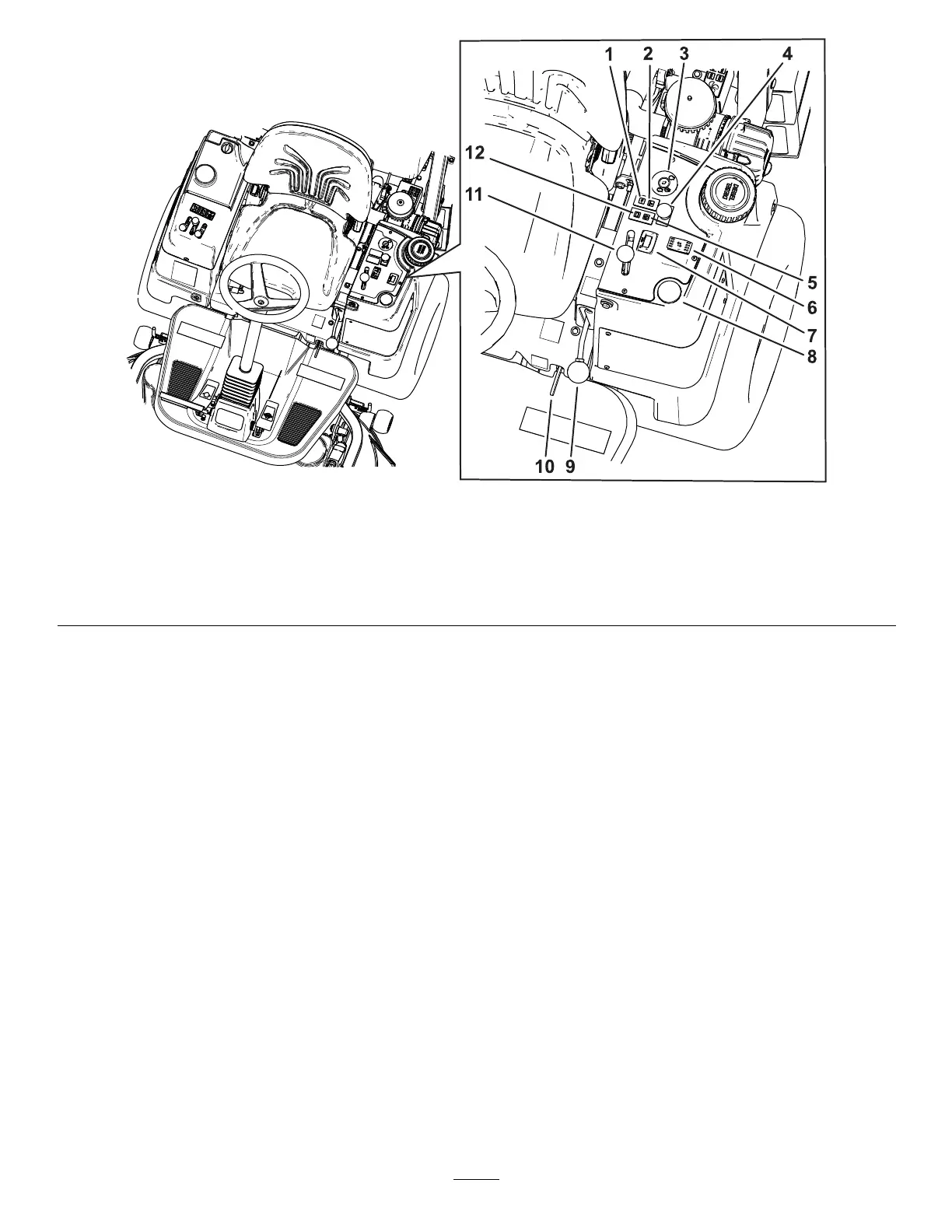
Figure 8
1. Oil-pressure warning indicator 5. Glow-plug indicator
9. Parking-brake lever
2. Engine-temperature warning indicator
6. Height-of-cut (HOC) switch 10. Platform latch
3. Key switch 7. Hour meter 1 1. Throttle lever
4. PT O switch
8. Fuel guage 12. Battery-charge indicator
Battery-Charge Indicator
The charge indicator ( Figure 8 ) illuminates if electrical
charging system is operating below the normal
operating range. Check and/or repair the electrical
charging system.
Glow-Plug Indicator
The glow-plug indicator ( Figure 8 ) glows red when the
glow plugs are activated.
Oil-Pressure W arning Indicator
The oil-pressure warning indicator ( Figure 8 )
illuminates if the engine-oil pressure drops below
a safe level while the engine is running. If the light
ickers or remains on, stop the machine, shut of f the
engine, and check the oil level. If the oil level is within
the acceptable range, but the light does not go out as
the engine runs, shut of f the engine immediately and
contact your authorized T oro distributor for assistance.
Check the operation of warning light as follows:
1. Engage the parking brake.
2. T urn the key switch to the O N /P REHEAT position,
but do not start the engine.
Note: The oil-pressure light should glow red.
If the light does not function, either a bulb is
burned out or there is a malfunction in the
system which must be repaired.
Engine-T emperature Indicator
The engine-temperature indicator ( Figure 8 )
illuminates if cooling system is operating above the
normal operating range. Check and/or repair the
cooling system.
PT O Switch
The PT O switch ( Figure 8 ) has 2 positions: O UT
(engaged) and I N (disengaged). Pull out the PT O
switch to engage the implement or cutting-unit blades.
Push in the button to disengage the implement
operation.
Note: If you leave the operator ’ s seat while the PT O
switch is in the O N position, the machine automatically
shuts of f the engine after a 1-second delay; refer to
Checking the Safety-Interlock System ( page 25 ) .
18