DiodeAssembly
g295056
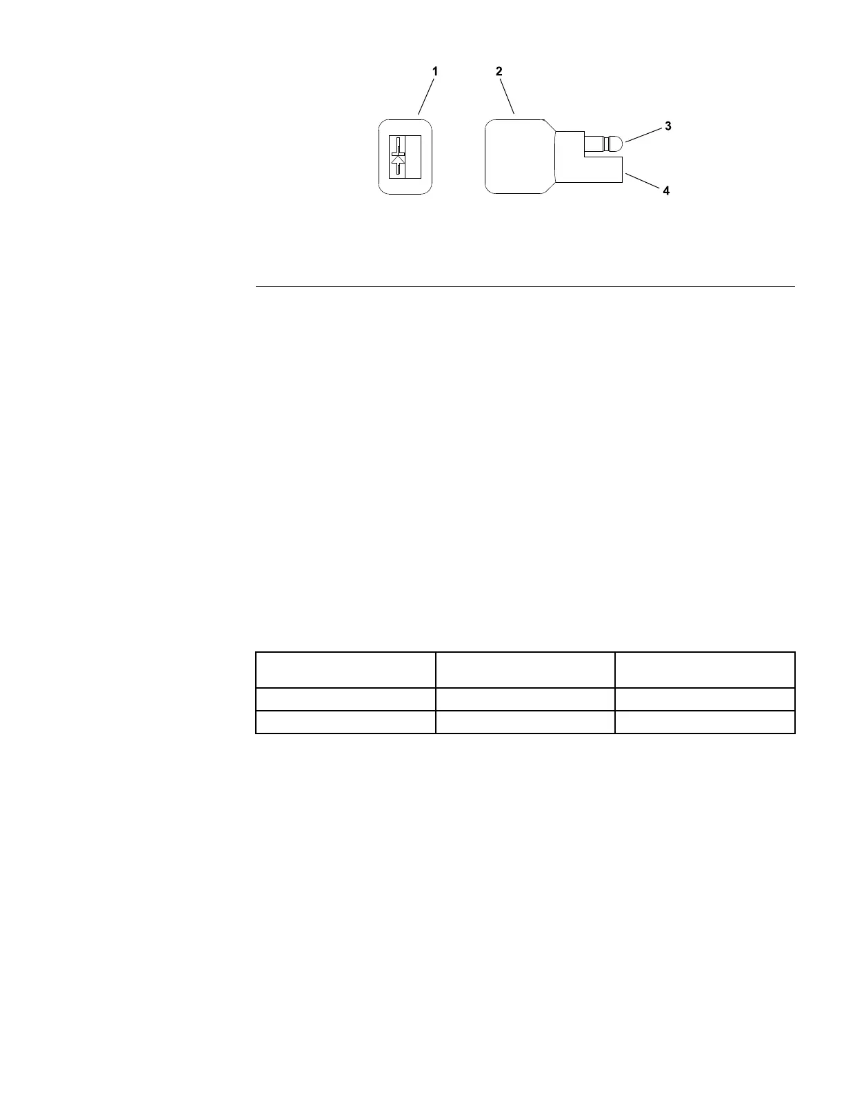
Figure137
1.Endofthediodebody
3.Maleterminal
2.Diodeassembly4.Femaleterminal
Thediodeassemblyisusedinthemainwireharness.Thediodecanbe
identiedbytheirblackcoloranddiodesymbolontheendofthediodebody.
ThediodeassemblyisusedtoprotectthePTOclutchfromreversepolarity
intheelectricalcircuit.
Thediodeassemblyisusedtoprotecttheengineshutoffsolenoidfromvoltage
spikesintheelectricalcircuit.
TestingtheDiodeAssembly
1.Parkthemachineonalevelsurface,lowerthecuttingdeck,shutoffthe
engine,settheparkingbrake,andremovethekeyfromthekeyswitch.
2.LocateandgetaccesstothediodeassemblynearPTOelectricclutchnear
theengineandremovecabletiethatsecuresdiodetowireharness.Unplug
thediodefromthewireharnessfortesting.
3.Thediodecanbetestedusingadigitalmultimeter(diodetestorohms
setting);refertoDiodeT estT able(page6–43).
DiodeTestTable
MultimeterRedLead(+)
onTerminal
MultimeterBlackLead
(-)onTerminal
Continuity
FemaleMaleYes
MaleFemaleNo
4.Iftestingdeterminesthatdiodeisfaulty,replacediodeassembly.
5.Afterdiodetestingiscomplete,makesurethatdiodeisfullyinstalledintowire
harnessconnectorandsecuredtoharnesswithcabletie.
ProLineH800
Page6–43
ElectricalSystem:TestingtheElectricalComponents
19241SLRevB

 Loading...