CHAPTER 5 TPCL-LE MODE (INTERFACE COMMANDS)
B-EP Series
5-133
(12) Link field No.
The link field No. can be programmed by designating it after the symbol “;.”
After the link field No. is designated using the Format Command, the data strings are
linked by the Link Field Data Command to draw an image.
Up to 20 fields can be linked.
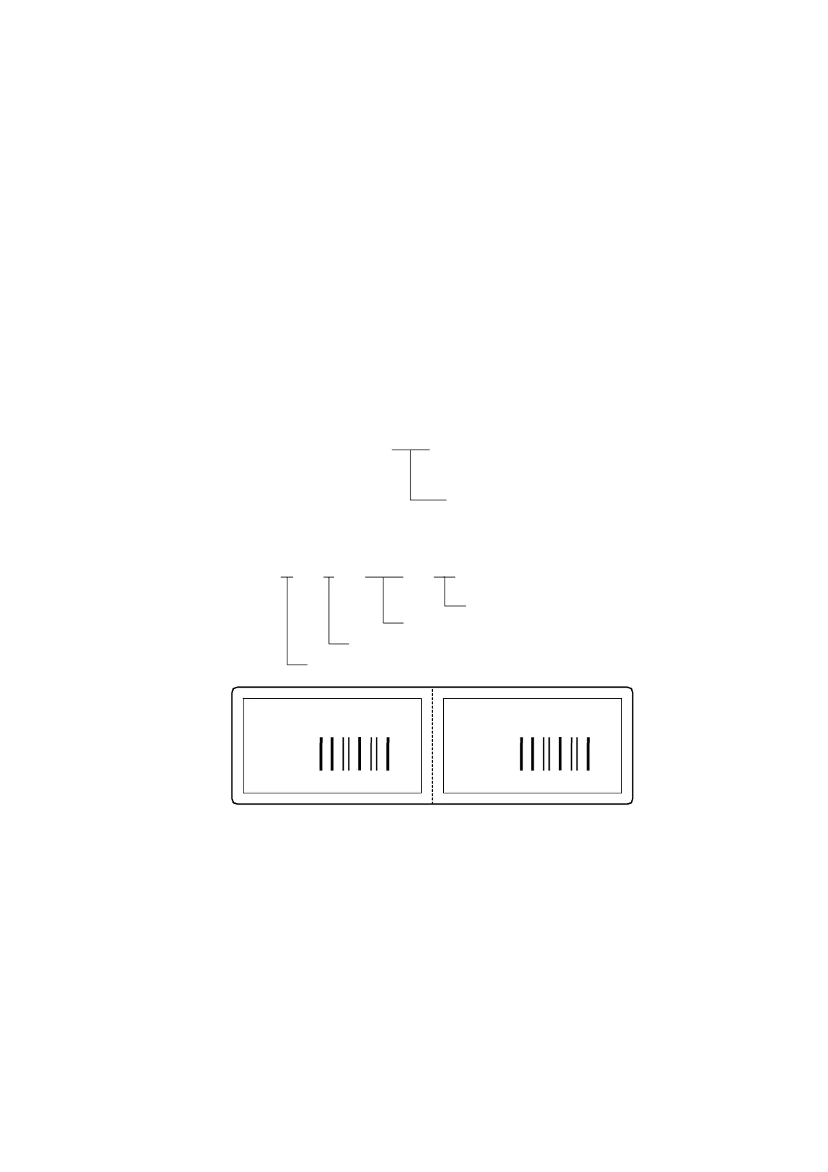
The following shows an example of linked fields on the two continuous labels.
[Format Command]
[ESC] PC01; ........................ ; 01 [LF] [NUL] : Link field No. 1 is designated.
[ESC] PC02; ........................ ; 03 [LF] [NUL] : Link field No. 3 is designated.
[ESC] PC03; ........................ ; 04 [LF] [NUL] : Link field No. 4 is designated.
[ESC] XB01; ................... ; 03, 04 [LF] [NUL] : Link fields No. 3 and No. 4 are
designated.
[ESC] PC04; ........................ ; 02 [LF] [NUL] : Link field No. 2 is designated.
[ESC] PC05; ........................ ; 03 [LF] [NUL] : Link field No. 3 is designated.
[ESC] PC06; ........................ ; 04 [LF] [NUL] : Link field No. 4 is designated.
[ESC] XB02; ................... ; 03, 04 [LF] [NUL] : Link fields No. 3 and No. 4 are
designated.
Designating link field No.
[Data Command]
[ESC] RB; A [LF] B [LF] ABCD [LF] 001 [LF] [NUL]
Link field No. 4
Link field No. 3
Link field No. 2
Link field No. 1
A
ABCD
001
*ABCD001*
B
ABCD
001
*ABCD001*
 Loading...