3
© 2013-2017 TOSHIBA TEC CORPORATION All rights reserved
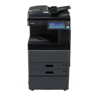
e-STUDIO2006/2306/2506/2007/2307/2507/2303A/2303AM/2803AM/2309A/2809A
OUTLINE OF THE MACHINE
3 - 33
3.8 Scanner
3.8.1 General Description
In the scanning section, this equipment uses a CIS (Contact Image Sensor) for scanning the image.
The surface of an original is irradiated with light from the LED array mounted on the CIS unit and the
reflected light is scanned by the CMOS sensor where the optical image data are converted into an
analog electrical signal, and then transmitted to the MAIN board. After the binarization and the various
image processing operations necessary for image formation are performed on the MAIN board, the
data are transmitted to the writing section.
Fig. 3-37
[1] RADF original glass
[2] Original glass
[3] CIS
[4] Scan motor (M1)
[5] Platen sensor (S7) <20H/23H/25H, 23HA/28HA only>
[6] Automatic original detection sensor-1 (S9) <20H/23H/25H, 23HA/28HA only>
[7] Automatic original detection sensor-2 (S10) <20H/23H/25H, 23HA/28HA only>
[1]
[3]
[2] [6][7]
[4][5]

 Loading...