Do you have a question about the Toshiba e-studio281c and is the answer not in the manual?
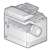
Details about the copier's specifications, including type, process, original table, accepted originals, and copy speed.
Lists accessories included with the machine, such as manuals, cables, stickers, and developer materials.
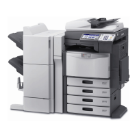
Lists optional components that can be added to the machine, like RADF, finishers, and memory.
Lists consumables required for the machine's operation, such as toner cartridges, developer, and drums.
Provides a diagram illustrating the system configuration and interconnected components.
Lists error codes, their classification, contents, and troubleshooting steps.
Details error codes related to paper jams, including paper exit, other paper jams, and misfeeding.
Lists service call codes related to motor abnormalities, scanning system issues, and circuit errors.
Lists errors related to internet fax and scanning functions, including RFC and file sharing errors.
Lists error codes related to printer functions such as page memory size, HDD full, and limit over errors.
Explains how to enter and use various self-diagnosis modes like control panel check, test mode, and adjustment mode.
Details how to check input signals using test mode 03, covering various buttons and their highlighted states.
Explains how to check output signals by entering specific codes in test mode 03, listing various functions and their procedures.
Describes how to print embedded test patterns by keying in specific codes in test print mode 04.
Explains how to enter and use the adjustment mode (05) to correct or change various items.
Details how to set or change items within the setting mode (08), outlining procedures for different operations.
Explains the pixel counter function, factors affecting toner consumption, and how to view/clear data.
Provides a consolidated list classifying adjustment and setting modes by their respective codes.
Explains the order for image-related adjustments and the components involved.
Outlines procedures for automatic gamma adjustment and image quality control initialization.
Covers adjustments for image dimensions, including paper alignment and scanner-related settings.
Provides an overview of various image dimensional adjustment items and the required order of operations.
Explains how to adjust the paper alignment amount using specific codes and paper types.
Details printer-related adjustments performed using a printed grid pattern and specific codes.
Outlines adjustments for scanner-related issues like image distortion and reproduction ratios.
Covers image quality adjustments for the copying function, including gamma and color balance.
Details the automatic gamma adjustment procedure for the copying function.
Explains how to adjust gamma balance for black mode.
Describes adjusting background and text density using specific codes.
Explains how to adjust the judgment threshold for ACS in scanning.
Explains how to adjust scan image sharpness by balancing moire and sharpness.
Details setting range correction for scanning.
Explains background peak adjustment for range correction.
Details how to adjust smudge/faint text in black mode for better text improvement.
Explains the four modes of one-touch adjustment for highlighter, including switching between modes.
Details setting the beam level for 4-divided smoothing in black mode to adjust dot size.
Explains how to control the maximum toner amount adhering to the paper based on paper type.
Details adjusting the maximum text density for each color in full color mode.
Explains how to adjust text/photo reproduction levels for different modes and paper types.
Covers image quality adjustments specifically for the printing function.
Details the automatic gamma adjustment procedure for the printing function.
Explains how to adjust color deviation for the printing function.
Describes gamma balance adjustment for black mode.
Details color balance adjustment for color mode.
Explains how to adjust gamma balance for black mode.
Covers image quality adjustments for the scanning function.
Details gamma balance adjustment for scanning.
Explains density adjustment for black mode in scanning.
Details background adjustment for gray scale mode.
Explains background adjustment for color mode.
Explains how to adjust the judgment threshold for ACS in scanning.
Explains how to adjust sharpness for scanned images.
Details setting range correction for scanning.
Explains background peak adjustment for range correction.
Details fine adjustment of black density for scanned images.
Explains how to select the color space conversion method for scanned images.
Details reproduction ratio adjustment for primary scanning in black images.
Explains reproduction ratio adjustment for primary scanning in color images.
Details settings related to the high-voltage transformer and its outputs.
Provides a general description of high-voltage transformer outputs and important precautions.
Covers adjustments for the scanner section, including carriages and lens unit.
Details the installation and adjustment of carriage wires and positions.
Explains the procedure for replacing and installing the lens unit.
Outlines adjustments for the paper feeding system, particularly for sheet sideways deviation.
Details how to adjust guides to correct sheet sideways deviation in bypass and drawer feeding.
Explains adjustments for the developer unit, specifically the doctor-to-sleeve gap.
Provides a procedure for adjusting the doctor-to-sleeve gap for the black developer unit.
Details the procedure for adjusting the doctor-to-sleeve gap for the color developer unit.
Explains how to adjust the lift up/down timing for the black developer unit lever.
Covers various adjustments for the RADF unit, including position, height, skew, and leading edge.
Details the procedure for checking and adjusting the RADF position.
Explains how to check and adjust the RADF height.
Details the procedure for adjusting paper skew in simplex and duplex copying using the RADF.
Outlines the procedure for adjusting the leading edge position in simplex and duplex copying.
Explains how to adjust the horizontal position of the image based on the center line.
Details adjusting the copy ratio by measuring image dimensions against a chart.
Explains how to adjust the RADF opening/closing sensor bracket position.
Covers various adjustments for the MJ-1022 finisher, including jogging plate and stack tension.
Details the procedure for adjusting the jogging plate width.
Explains how to adjust the angle of the jogging plate for proper paper alignment.
Details adjusting the overlap between the sensor and flag for proper operation.
Explains how to adjust the tension of the stack processing motor belt.
Describes the procedure to release the stack tray guide lever fixing plate.
Outlines how to adjust the upper tray angle for proper paper alignment.
Explains how to simulate various functions by setting DIP switches on the finisher controller PC board.
Covers adjustments for the MJ-1023/1024 finisher, including alignment and stapling positions.
Details how to adjust the alignment position of the finisher unit.
Explains how to adjust the stapling position for front/rear stitches.
Details adjusting the folding position for the saddle stitcher unit.
Explains how to fine-tune the binding/folding position.
Details sensor output adjustment for the puncher unit.
Explains how to register the number of punch holes for the puncher unit.
Covers adjustments for the MJ-1101 finisher, including alignment and stapling positions.
Details how to adjust the alignment position of the finisher unit.
Explains how to adjust the stapling position.
Details setting the B4-size recycled paper mode to address paper catching issues.
Explains the PM support mode, its general description, operational flow, and screens.
Provides an overview of the PM support mode's purpose and capabilities for parts replacement timing.
Details the operational flow and screens within the PM support mode for checking and clearing counters.
Outlines general descriptions and preparation steps for performing PM procedures.
Lists operational items and their timing for overhauling the equipment.
Provides a checklist for preventive maintenance tasks across various units like scanner, laser, and feed units.
Lists the components included in various PM kits for different units.
Lists special tools (jigs) required for maintenance and adjustment procedures.
Provides a list of greases used for lubrication and their corresponding part names and volumes.
Details precautions for storing and handling consumables like toner, drums, and blades.
Provides specific storage precautions for toner, developer, drums, and paper.
Explains how to check and clean the photoconductive drum, including handling precautions.
Details handling precautions and cleaning procedures for drum and transfer belt cleaning blades.
Provides handling precautions for the drum cleaner brush.
Outlines handling precautions for the transfer belt, including cleaning and replacement.
Details checking and cleaning procedures for the fuser belt and pressure roller.
Explains how to check and replace oil and cleaning rollers for poor cleaning.
Details checking and cleaning procedures for the discharge brush.
Provides a diagnostic guide for various error codes, starting with paper transport jams.
Details troubleshooting steps for paper jams occurring at the paper exit section, including sensor and clutch checks.
Covers troubleshooting for paper misfeeding issues in ADU, bypass, and registration sensor areas.
Details troubleshooting for paper jams in various transport sections and clutches.
Lists troubleshooting steps for various other paper jams, including power-on jams and sensor issues.
Details troubleshooting procedures for jams caused by open covers in various sections like PFP, ADU, and finishers.
Lists troubleshooting steps for RADF jams, including sensor and cover-related issues.
Provides troubleshooting steps for various paper jams occurring in different finisher sections and motors.
Lists service calls related to motor abnormalities in drive systems.
Details service calls related to abnormalities in the PFP motor.
Covers service calls related to scanner issues like peak detection and carriage home position.
Lists service calls related to abnormalities in the fuser unit, including thermistor/heater and IH control issues.
Details service calls related to communication errors between different boards and units.
Mentions no specific service calls for RADF, but covers circuit-related issues.
Covers connection errors between various boards and abnormalities in components like engine-CPU and LGC board.
Details service calls related to laser optical unit issues like polygonal motor and H-Sync detection.
Lists service calls related to motor abnormalities in the finisher unit.
Covers service calls related to image quality sensor abnormalities.
Addresses common image quality issues like color deviation and uneven pitch.
Details troubleshooting for uneven pitch and jitter in scanned or printed images.
Explains troubleshooting steps for poor image density, color reproduction, and gray balance.
Outlines troubleshooting steps for background fogging in images.
Details troubleshooting for moire patterns and lack of sharpness in scanned images.
Explains troubleshooting for toner offset issues, including fuser unit and paper checks.
Covers troubleshooting steps for blurred images, involving scanner, drum, and ozone exhaust.
Details troubleshooting for poor fusing, including checks on IH electrics, rollers, and paper.
Outlines troubleshooting steps for blank prints, involving exposure lamp and main charger checks.
Details troubleshooting for white banding issues in the feeding direction.
Explains troubleshooting for white banding issues perpendicular to the feeding direction.
Covers troubleshooting for paper skew or slantwise copying.
Details troubleshooting steps for color banding issues.
Outlines troubleshooting steps for poor cleaning issues affecting image quality.
Provides instructions for replacing PC boards and the HDD.
Details the procedure and cautions for replacing the HDD.
Explains the procedure and settings required after replacing the SYS board.
Outlines the procedure for replacing the SLG board and related data transfers.
Details procedures for replacing or clearing NVRAM, including necessary settings.
Provides cautions related to data overwriting kit installation and HDD/SYS board disposal.
Explains how to display HDD operation history for diagnosing potential failures.
Discusses other potential errors, particularly related to wireless LAN connection issues.
Details the process of updating firmware using a download jig, including types of firmware and procedures.
Explains how to update firmware using the PWA-DWNLD-350-JIG2 download jig.
Describes the process of writing data to the download jig using a ROM writer adapter.
Details the procedure for updating firmware using the K-PWA-DLM-320 download jig.
Explains how to update firmware using a USB storage device, including requirements and procedures.
Provides appendix information related to firmware updating, including assist modes.
Lists the output channels and their destinations for the power supply unit.
Details the fuse types and their corresponding boards/parts for troubleshooting power issues.
Provides a diagram illustrating the configuration of the power supply unit and its connections.
Explains the auto supply order function for toner and used toner containers.
Provides an overview of the auto supply order process, including FAX and E-mail methods.
Details the required settings for enabling the auto supply order function.
Outlines the step-by-step procedure for setting up the auto supply order.
Shows the format of the order sheet for supplies.
Explains the service notification function for notifying technicians of equipment status.
Provides an overview of the service notification function and the items it notifies.
Details the preparation and setting procedure for the service notification function.
Lists the specific items that are notified via E-mail or FAX, including counter data and error history.
Details the procedure for backing up user data, setting items, and SRAM data using a USB storage device.
Explains the procedure for restoring user data, setting items, and SRAM data from a USB storage device.
Shows the AC wire harness connection diagram.
Provides the DC wire harness connection diagram.
Illustrates the layout of various electric parts within the machine.
| Print Speed (Black) | 28 ppm |
|---|---|
| Processor Speed | 400 MHz |
| Copy Speed (Black) | 28 cpm |
| Copy Resolution | 600 x 600 dpi |
| Scan Resolution | 600 x 600 dpi |
| Maximum Paper Size | A3 |
| Connectivity | Ethernet, USB |
| Operating System Compatibility | Mac OS |
| Paper Size | A4, A5, Legal, Letter, Executive, Statement |
| Duplex Printing | Yes |
| Fax Transmission Speed | 33.6 Kbps (optional) |