Voyager Rooftop Unit Interface
BMTW-SVN01F-EN 137
Voyager Rooftop Unit Interface
Description
Tracer Summit can monitor, control, and configure Voyager rooftop units.
The Voyager interface provides a communication link between the BCU
and each Voyager rooftop unit. For specific information about the number
of Voyagers allowed per BCU and per communication link, refer to
Table 7 on page 46.
Type of Communication Card: Comm3 or Comm4
Refer to “Isolated Comm3 Card” on page 49 and “Comm4 Card” on
page 51.
Voyager rooftop units must have the Trane communication interface
(TCI-3) module installed in order to communicate with Tracer Summit.
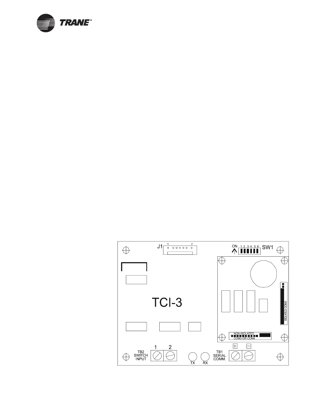
The daughter board on the TCI-3 must be configured for a “non-isolated
Comm3 or Comm4 card” (see Figure 63) when connected to a BCU
Comm4 link. Tracer Summit includes isolated Comm3 support, which
allows the Voyager to communicate to a BCU isolated Comm3 link. When
using this configuration, the TRI-3 daughter board must be configured for
“isolated Comm3” by rotating the daughter board clockwise 90° from the
position shown in Figure 63 so that “Isolated Comm3” is at the bottom.
Refer to the Trane Communication Interface (TCI-3) installation, opera-
tion, and maintenance literature for more information on configuring the
TCI-3.
Figure 63. Location of Address DIP Switches and Communication-Link
Terminations on the Voyager Rooftop Unit UCM