Chapter 5 UCM Wiring and Addressing
114 BMTW-SVN01F-EN
Device Addressing
Each UCM must have a unique address on each link. TRSs can have an
address from 0 through 15. Set the address of each TRS on the communi-
cation card in Slot 9 of the TRS card cage. The TRS address is set with
the S1 address DIP switches on the communication card. The DIP switch
settings for the valid addresses are shown in Table 21.
Note:
Since the TRS interface feature of Tracer Summit is used pri-
marily in retrofit or migration applications, the TRS communi-
cation addressing should already be configured. However, due
to BCU capacity and loading, it may be necessary to split an
existing TRS link containing up to 16 TRS panels into multiple
links with fewer UCMs. In this case, it may be prudent to leave
the TRS communication-link addresses as configured and set
up the BCU to communicate at those addresses.
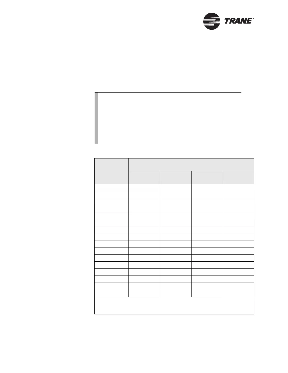
Table 21. TRS Address Settings
UCM Address
TRS Switch S1 DIP Switch Settings
S1-1 S1-2 S1-3 S1-4
0 CLOSED CLOSED CLOSED CLOSED
1 open CLOSED CLOSED CLOSED
2 CLOSED open CLOSED CLOSED
3 open open CLOSED CLOSED
4 CLOSED CLOSED open CLOSED
5 open CLOSED open CLOSED
6 CLOSED open open CLOSED
7 open open open CLOSED
8 CLOSED CLOSED CLOSED open
9 open CLOSED CLOSED open
10 CLOSED open CLOSED open
11 open open CLOSED open
12 CLOSED CLOSED open open
13 open CLOSED open open
14 CLOSED open open open
15 open open open open
Note:
Actual TRS DIP switch labels are OPEN and CLOSED. On this address table, open = off
and closed = on.