Communication-Link Wire
BMTW-SVN01F-EN 59
Termination Resistor placement for Comm3 and
Comm4 links
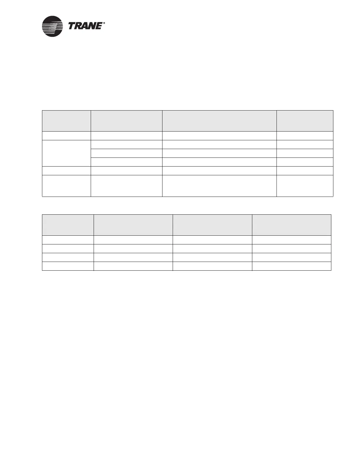
Table 8 and Table 9 describe when termination resistors are needed and
where to place them.
Termination Resistance Placement for Comm5 Links
To correctly install a Comm5 link, termination resistors are required.
For correct termination placement, follow the guidelines below:
• Terminate a daisy chain configuration with a resistor at each end of
the wire (105
Ω. for 22 AWG, Level 4 wire and 82 Ω. for18 AWG,
Trane “purple” wire).
• If a repeater is used, each link of the configuration that is created by
the repeater requires termination resistors (see “Alternate Daisy
Chain Resistor Placement” on page 60).
• Trane recommends that only one type of wire should be used for the
Comm5 communication link.
• A set of as-built drawings or a map of the communication wire layout
should be made during installation. Any sketch of the communication
layout should feature the terminating resistor placement (see
Figure 27 and Figure 28 on page 60 for daisy chain configurations).
Table 8. Termination Resistor Placement for Daisy Chain Configurations
Communication
Link
Wire Length Resistance Resistor Placement
2 Any Not required —
3
0–800 ft (0–244 m) 300 Ω At far end of link
800–2,500 ft (244–762 m) Not required —
> 2,500 ft (762 m) 300 Ω At far end of link
4 Any Not required —
5 Any 105 Ω for 22 AWG, Level 4 communication
wire. 82 Ω for 18 AWG, Trane “purple”
comm wire
At each end of link
Table 9. Termination Resistor Placement for Branch Configurations
Communication
Link
Wire Length Resistance Resistor Placement
2Any Not required —
3Any Not required —
4Any Not required —
5 Not recommended Not recommended Not recommended