Chapter 10 BCU Operation and Communication Status
200 BMTW-SVN01F-EN
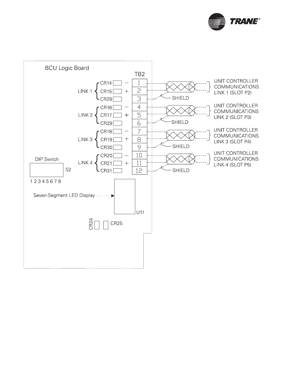
Figure 93. BCU Logic Board LED Locations
LED Indicators for BCU Communication
Status
A row of green, yellow, and red LEDs, identified by numbers beginning
with CR and located to the left of the T2 terminal block on the BCU logic
board (see Figure 93), indicates the status of communication between the
BCU and UCMs. CR28 through CR31 pertain to only Comm5 communica-
tion.