Chapter 5 UCM Wiring and Addressing
102 BMTW-SVN01F-EN
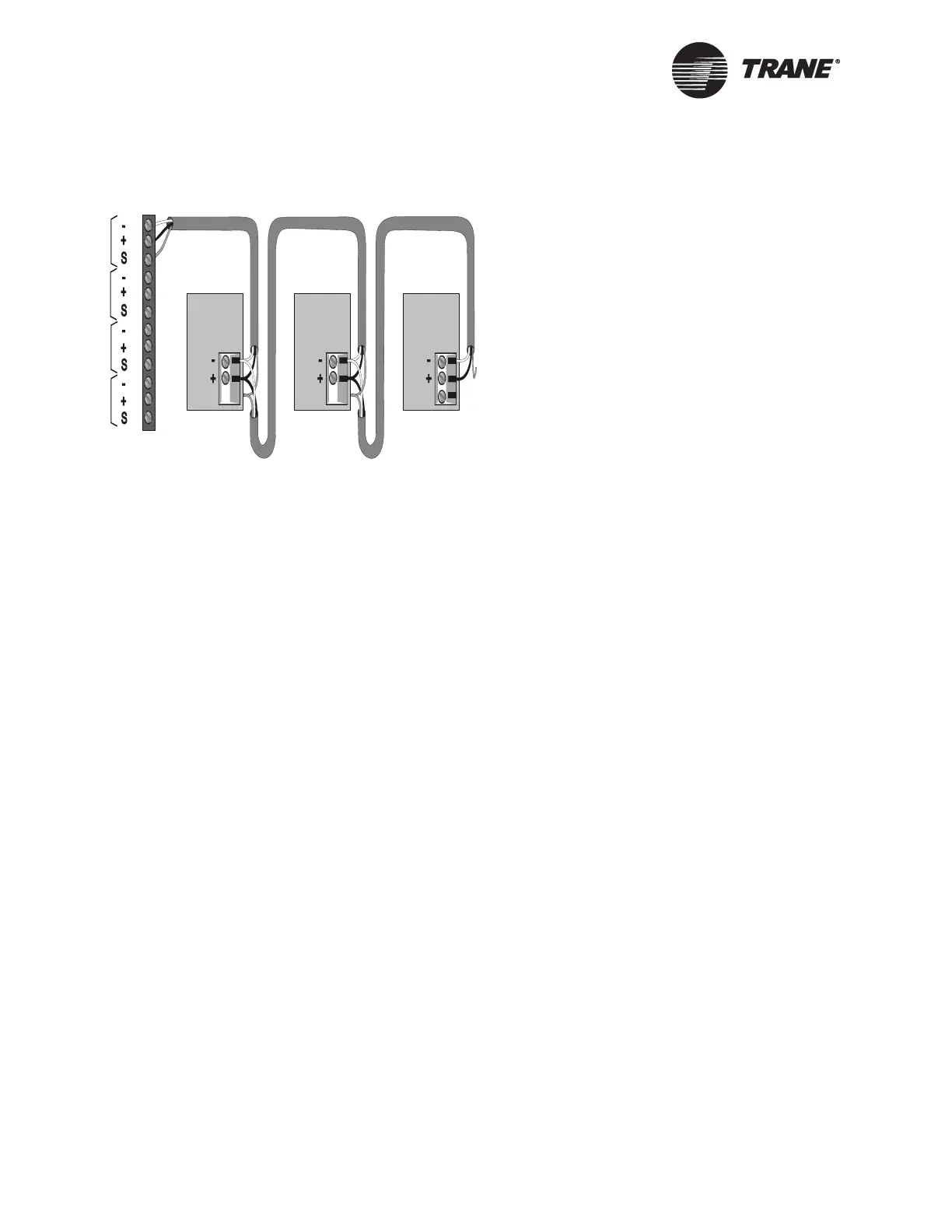
Figure 49. ICS Connections Between the BCU and U.S.-built Scroll
Chiller (CGA/CGW and CGAF) UCMs on an Isolated Comm3 Link
Device Addressing
Each UCM must have a unique address that is set using a DIP switch on
the scroll chiller. For CGA/CGWs, the location of the address DIP
switches is shown in Figure 47 on page 100. For address DIP switch set-
tings for CGA/CGWs, refer to Table 17 on page 103.
For CGAFs, addresses are set from the front panel. Refer to the CGAF
installation, operation, and maintenance manual for details.
Device #3
Comm Link
Terminal Block
Device #1
Cut and tape
the shield
wires together.
Device #2
Cut and tape
the shield
wires together.
Cut and tape
back the
shield wire.
1
2
3
4
5
6
7
8
9
10
11
12
Link 1
Link 2
Link 3
Last device on
the Comm4 link
Shield Shield Shield
Comm Link
Terminal Block
Comm Link
Terminal Block
Link 4