Chapter 1 Before Installation
12 BMTW-SVN01F-EN
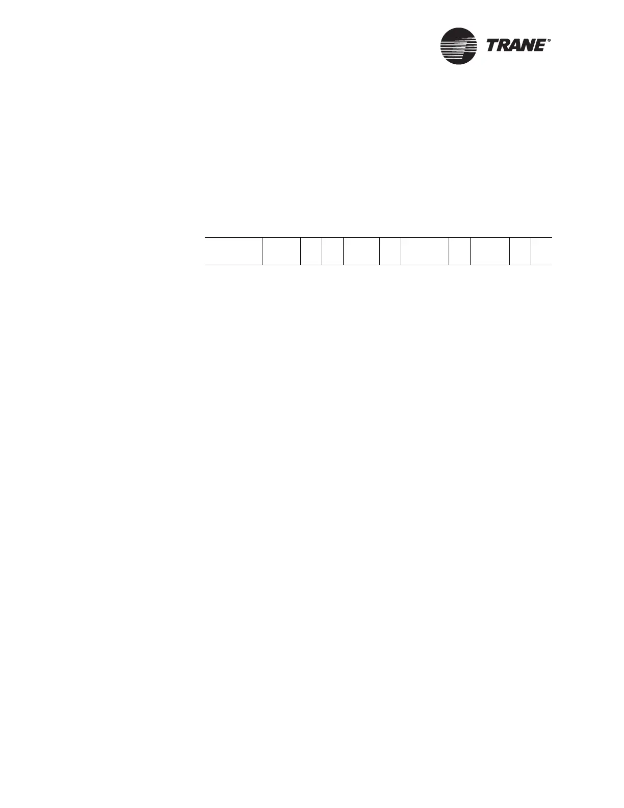
Model Number Description
All Trane products are identified by a multicharacter model number that
precisely identifies a unit. This number is located on the BCU nameplate.
The model number code for Tracer Summit systems is described in
Figure 3. Its use enables installing contractors, owner/operators, and ser-
vice technicians to determine components, operation, and options for a
particular system.
Figure 3. Model number example
1–4
Tracer Summit for Windows building management systems
5–7
Not used
8
Input power supply
A = 120 Vac/50,60/1
B = 120/240 Vac/50,60/1 for international
C = 240 Vac/50,60/1 for EC
D = 120 Vac/50,60/1 for UL-864-UUKL
9
Model
A = factory assigned
10,11 Design sequence
0A = factory assigned
12
BCU capacity
0 = standard capacity
1 = high capacity
13–16UCM communication cards
0 = none
1 = Comm2 (UCP1)
2 = Comm3 (PCM, TCM, Trane Europe chiller, RTA/RTW, SWUD, CGAS/CGWD, CCP)
3 = Comm3 non-isolated (VAV1, TRS panels)
4 = Comm4 (UCP2, UPCM, VAV II/III/IV, TUC, IntelliPak, Voyager)
5 = Comm5 (Tracer controllers and generic LonTalk
®
devices)
17
A = none
18–20
Internal card options
0 = none
1 = ARCNET coax*
2 = ARCNET fiber*
3 = ARCNET hub 3 coax*
4 = ARCNET hub 1 fiber 2 coax*
5 = ARCNET hub 2 fiber 1 coax*
6 = EIA-232 port
7 = internal modem
8 = Ethernet card
*Not available with the EC version
21
Operator Display
0 = none
1 = Touch screen display
22
Local I/O module
0 = none
1 = 5 universal inputs/1 binary output
BMTW
1-4
000
5-7
A
8
A
9
0A
10,11
0
1
2
1345
13–16
A
17
378
18–20
0
21
1
22