Chapter 5 UCM Wiring and Addressing
72 BMTW-SVN01F-EN
Type of Communication Card: Comm4
Refer to “Comm4 Card” on page 51.
Wiring Notes
To establish wiring connections between the UCM and the BCU, Trane
requires that you use the communication-link wiring specified in this
manual. For wire selection specifications, see “UCM Communication-
Wire Characteristics” on page 55.
Use fiber-optic modems for building-to-building communication. If fiber
optics are not used, building-to-building communication wiring requires a
Transtector transient protector at each building. You can purchase Tran-
stector protectors through Trane. Contact your local Trane sales office for
details.
In a daisy chain configuration, use one pair of wires that start at the BCU
and go to all UCMs in a continuous loop. A branch configuration is possi-
ble if you need to tap into a daisy chain. Limit the total aggregate length
of the wiring for each communication link to 5,000 ft (1,524 m).
To connect communication wiring:
1. Attach one end of the communication-link wiring to TB2 on the BCU.
For the location of TB2, refer to Figure 16 on page 47.
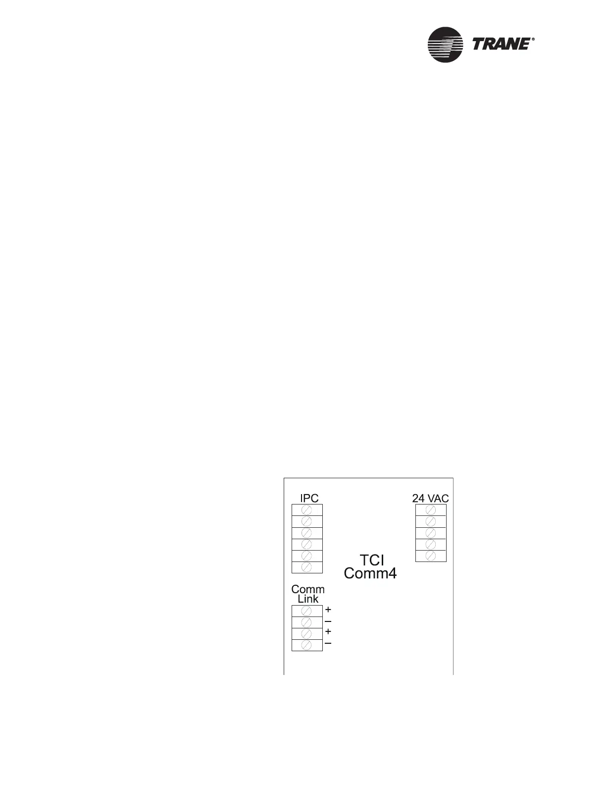
2. Attach the other end of the communication-link wiring to the chiller
TCI Comm4 module on the communication-link terminal. For the
location of the communication-link terminations on the chiller TCI
Comm4 module, see Figure 34.
Figure 34. Location of UCM Communication-link Terminations on the
TCI Comm4 Link