Installing the Optional Operator Display
BMTW-SVN01F-EN 35
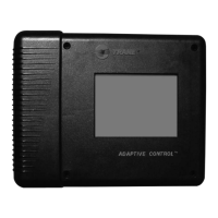
Figure 11. Operator display screw hole locations
10. Thread another screw into the hole in the upper right side of the BCU
chassis. Do not completely tighten the screw.
11. Hook the BCU operator display assembly onto these two screws.
12. Thread the remaining two screws into the lower- left and lower-right
corners of the operator display.
13. Tighten all four screws.
14. Attach the loose end of the ribbon cable into P13, the 10-pin operator
display socket located on the BCU logic board (see Figure 12 on
page 36).
Note:
Align the polarizing key on the ribbon cable with the slot in the
operator display socket.