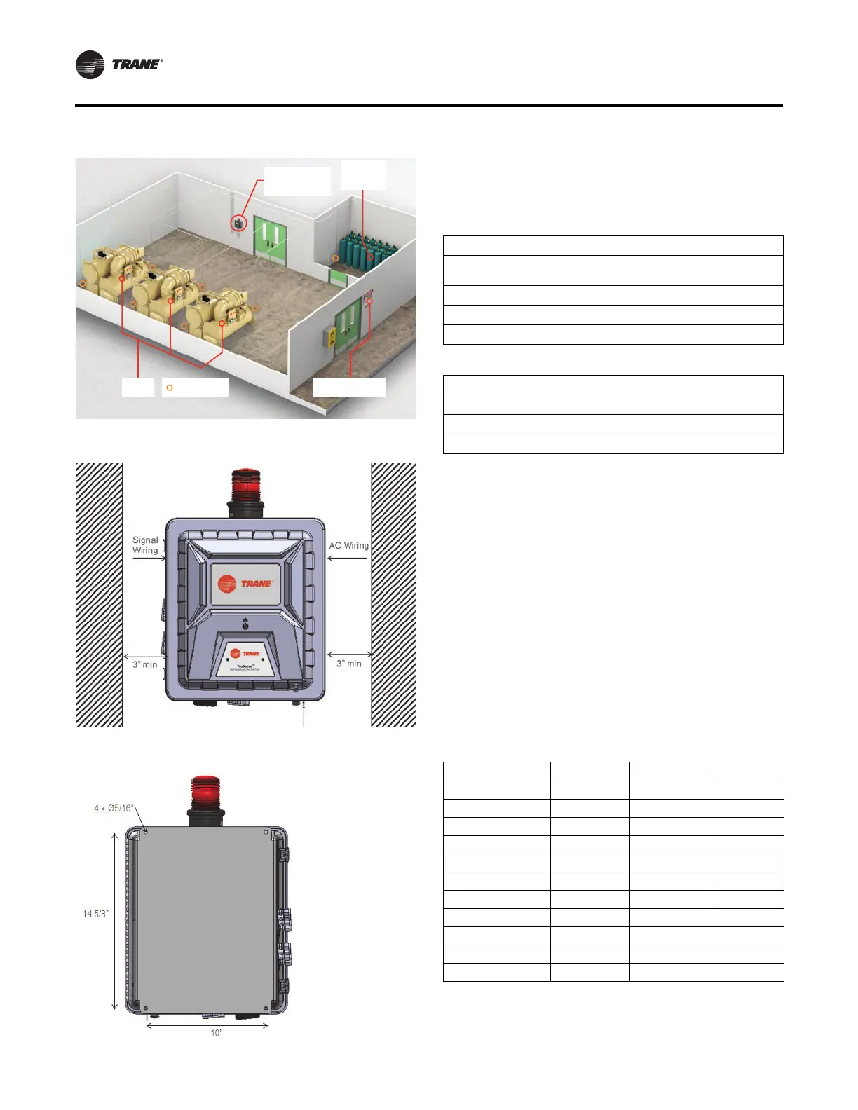
Figure 7. Mounting location
Figure 8. Front of device
Figure 9. Rear of device
Installation
12 RMWH-SVX001C-EN
Sample and Exhaust Lines
Tubing Material
The device can use hard and soft tubing. The following are
acceptable tubing types:
Imperial (I-P) Units
1/4-in. OD x 1/8-in. inside diameter (ID) Polyurethane tubing (ether-
based)
1/4-in. OD x 3/161/4-in. ID Polyuret
hane tubing (ether-based)
1/4-in. OD Copper tubing
1/4-in. OD Stainless steel tubing
International System (SI) Units
6-mm OD x 4-mm ID Polyurethane tubing (ether-based)
6-mm OD Copper tubing
6-mm OD Stainless steel tubing
Note: Use the appropriate tools to give a clean, smooth
end to the tubing when it is cut.
Routing and Placement
Trane recommends the use of at least two gas-monitoring
points per chiller for sufficient detection monitoring. Due
to installation and application variations, each system
must be analyzed individually.
Do a smoke test of the mechanical
room to determine the
flow patte
rn and allow for optimal placement of the
sample lines. For a list of approved parts and how to order
them, refer to “Ordering Information,” p. 52.
Keep the total line length of a
poi
nt, including the sample
line and exhaust line, at less than 1200 ft (366 m). Keep
lines as short as possible to minimize the transport time of
the device.
Table 4. Transport time
Line Length (ft) 4 pts 8 pts 16 pts
0 19 s 19 s 19 s
50 19 s 19 s 19 s
100 19 s 19 s 19 s
150 19 s 19 s 19 s
200 19 s 19 s 19 s
250 19 s 19 s 19 s
300 1 m 35 s 2 m 51 s 5 m 23 s
350 1 m 35 s 2 m 51 s 5 m 23 s
400 2 m 51 s 5 m 23
s 10 m 27 s
450 2 m 51 s 5 m 23 s 10 m 27 s
500 2 m 51 s 5 m 23 s 10 m 27 s
Note: Transport time is similar for all tubing
configurations.
TruSense
Refrigerant Monitor
Refrigerant
Storage
Chillers Sampling Points Entry Way Signalling