RMWH-SVX001C-EN 55
Appendix B: Installation of Optional Equipment
NOTICE
Electrostatic Discharge!
Electrostatic discharge can short equipment circuitry.
Ensure that you are properly grounded be
fore handling
sensitive electronic equipment.
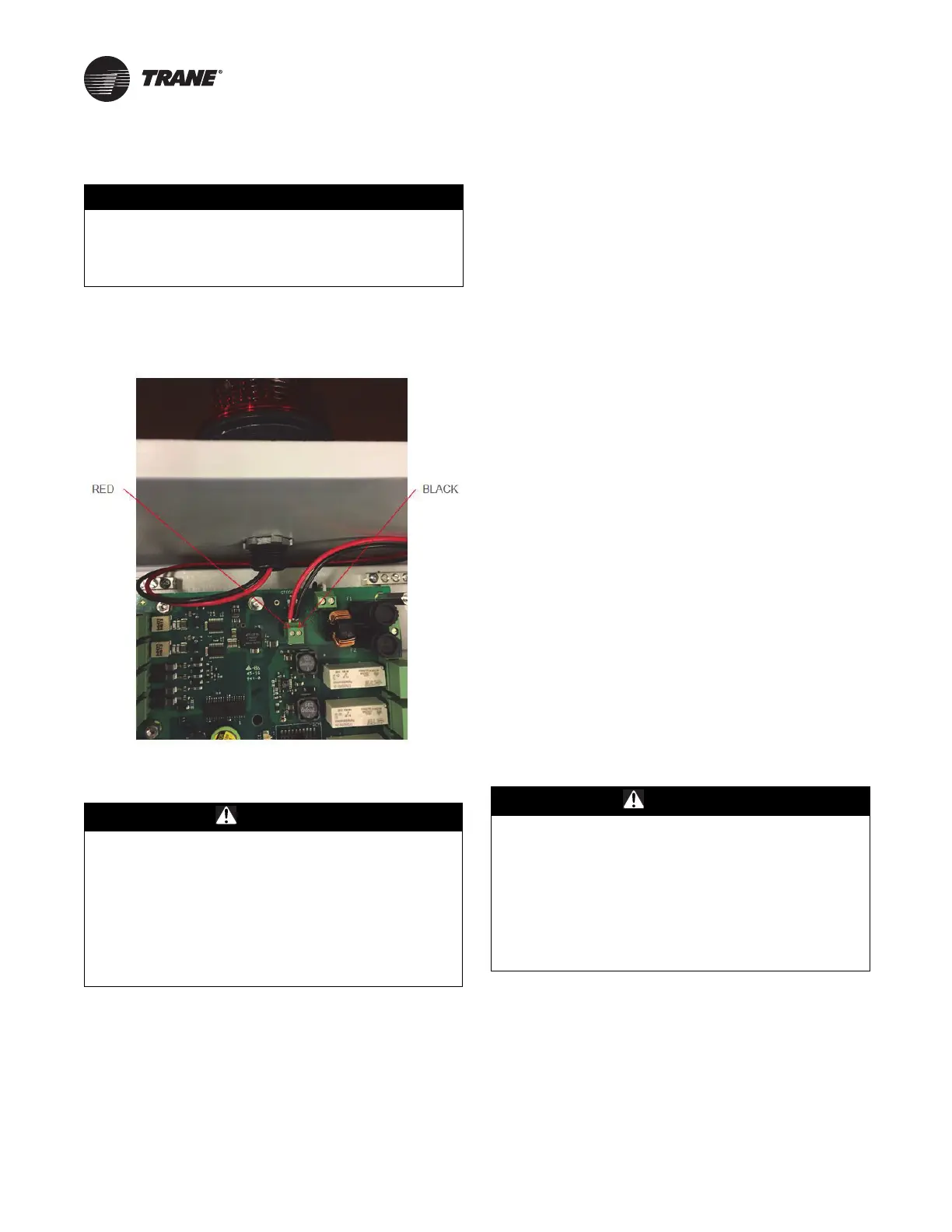
Strobe
Figure 16. Strobe wiring
For field installations, follow the strobe manufacturer’s
instructions and the following general procedure:
WARNING
Hazardous Voltage!
Failure to disconnect power before servicing could
result in death or serious injury.
Disconnect all electric power, including remote
disconnects before servicing. Follow proper lockout/
tagout procedures to ensure the power cannot be
inadvertently energized. Verify that no power is present
with a voltmeter. To prevent electrical shock, the circuit
board cover must be in place when power is on.
1. Disconnect electrical power to
the device.
2. I
f applicable, remove the lockin
g mechanism.
3. Release the two latches on the left side of the device.
4. Open the enclosure
.
5. Attach the ESD wrist strap to the ESD connection point
i
nside th
e enclosure.
6. Use a 1/4-in. hex driver to remove the four hex nuts on
the circuit board cover.
7. Remove the circuit board cover.
8. Remove the hole plug out of the top of the device.
9. Put the wires of the strobe
through the middle of the
supplied gasket.
10. Put the wires through the ho
le i
n the top of the
enclosure and the supplied locknut.
11. Tighten the locknut so the strobe is attach
ed securely
to the device.
12. Insert the wires for the strobe into
the Phoenix
connector on the circuit board marked “STROBE”.
Make sure each wire is inserted into the correct
connector terminal.
13. Use a small flathead screwdriver to tighten the screws
on
the Ph
oenix connector and secure the wires.
14. Install the circuit board cover.
15. Use a 1/4-in. hex driver to ins
tall the four hex nuts on
the ci
rcuit board cover.
16. Disconnect the ESD wrist strap from the ESD
connection
point inside the enclosure.
17. Close the enclosure.
18. Latch the two latches.
19. If applicable, attach
the locking mechanism.
20. S
upply electrical power to the device.
External Horn
For field installations, follow the horn manufacturer’s
instructions and the following general procedure:
WARNING
Hazardous Voltage!
Failure to disconnect power before servicing could
result in death or serious injury.
Disconnect all electric power, including remote
disconnects before servicing. Follow proper lockout/
tagout procedures to ensure the power cannot be
inadvertently energized. Verify that no power is present
with a voltmeter. To prevent electrical shock, the circuit
board cover must be in place when power is on.
1. Disconnect electrical powe
r to the device.
2. I
f applicable, remove the locking mechanism.
3. Release th
e two latches on the left side of the
device.
4. Open the enclosure.
5. Attach the ESD wrist strap to
the ESD conn
ection point
inside the enclosure.
6. Mount the horn 7–12 ft (2–4 m) above the floor.