Installation
RMWH-SVX001C-EN 13
Typically, refrigerants collect near the floor. Install the
sample points 12–18 in. (30–46 cm) above the floor.
For installations where water condens
ation in the sample
l
ines is likely, Trane recommends installing a water trap
filter such as a Parker P/N F504-01AHX67 or equivalent.
End-of-Line Filters
WARNING
Risk of Asphyxiation!
Failure to follow instructions below could cause
inaccurate readings and improper gas monitoring
which could result in death or serious injury.
Use and maintain end-of-line filters to ensure proper
readin
gs and prevent damage to internal components.
Make additional servicing necessary.
Install an end-of-line filter (Trane P/N FLR04743) in each
sample line to decrease contaminants in the sample lines
and device.
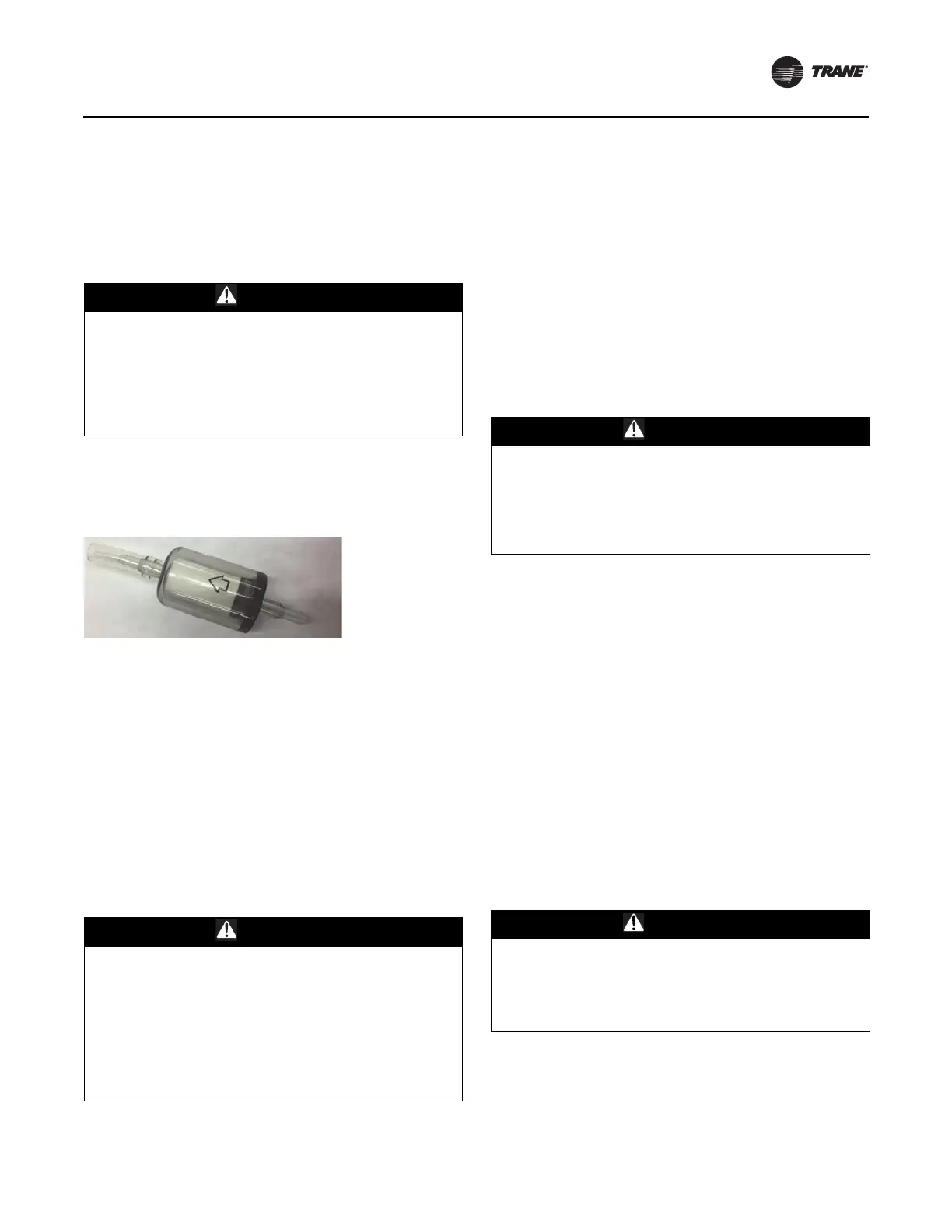
Figure 10. End-of-line filter
Do the following procedure to install end-of-line filters:
1. Remove the new
end-of-line filter from the bag.
2. Slide the end of the end-of-line filt
er wi
th flexible
tubing onto the sample line tubing. Make sure the
arrow on the body of the filter (refer to Figure 10) points
in the direction of air flow into the sample line.
Examine and replace the end-of-line filters at regular
intervals. The appropri
ate interval for replacement is
determined by the environment of the installation.
For a list of approved parts and how to order them, refer to
“Ordering Information,” p. 52.
Connections
WARNING
Risk of Asphyxiation!
Failure to follow instructions below could cause
inaccurate readings and improper gas monitoring
which could result in death or serious injury.
Install tubing with large enough b
end radii to prevent
kinking or pinching. Kinking or pinching of the tubing
could result in insufficient monitoring of an area. Before
connecting tubing to the device, clean all tubing with
compressed air or nitrogen to remove debris.
The device has Swagelok® compression fit
tings fo
r
connections to the sample and exhaust lines. These
fittings accept the hard and soft tubing specified in
“Tubing Material,” p. 12.
Do the following procedure to connect the sample and
exha
ust lines:
1. Remove the cap from the compression fitting.
2. Insert the tubing fully
into the compression f
itting and
against the shoulder.
3. Turn the nut until i
t is
finger-tight on the tubing.
4. Mark the nut at the 6 o’clock position.
5. While holding the body of the f
itting steady, tighten
the
nut 1-1/4 turns to the 9 o’clock position.
Exhaust Venting
WARNING
Risk of Asphyxiation!
Failure to follow instructions below could cause
inaccurate readings and improper gas monitoring
which could result in death or serious injury.
Make sure to remove the cap from the exhaust port
before operating the device.
The use of exhaust tubing reduces pump
noise from the
device.
Make sure to vent the exhaust of the device to the outside
atmosphere (preferred) or
a safe area.
Do not use inline or end-of-line filters in the exhaust line.
If possible, route the exhaust line so venting
occurs to the
outsi
de atmosphere. Make sure to protect the end of the
exhaust tube from elements such as water, dirt, snow, ice,
and insects, which can cause clogs and prevent efficient
venting.
If exhaust venting occurs indoors, make sure to route the
e
xhaust line to:
• An area that is not monitored for refrigeran
t gases
• An area away from personnel
Wiring and Grounding
WARNING
Proper Grounding Required!
Failure to follow instructions below could result in
death or serious injury from electrocution.
Make sure the device chassis is connected to the earth
ground at the ground bar.
Note:
• In
stallations that require conformity
to the CE mark
must have a connection between the TruSense™
RMWH Refrigerant Monitor device and a nearby earth
ground potential.