10
Table 10-1 General Data
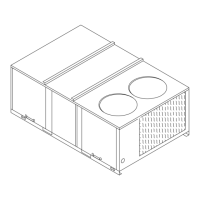
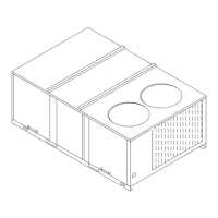
6¼ Ton Downflow
and Horizontal Single Compressor Dual Compressor
YC
✲060C1 YC✲060C3, C4, CW YC✲075C3, C4, CW YC✲090C3, C4, CW YC✲090D3, D4, DW
Cooling Performance
1
Gross Cooling Capacity 64,000 62,500 75,000 92,000 90,000
EER/SEER
2
—/9.85 —/10.00 9.00/— 9.00
8
/— 9.00
9
/—
Nominal CFM / ARI Rated CFM 2,000/2,000 2,000/2,000 2,500/2,188 3,000/2,625 3,000/2,625
ARI Net Cooling Capacity 61,500 60,000 72,000 88,000
8
86,000
9
Integrated Part Load Value
3
— — — — 9.4
9
System Power (KW) 6.95 6.71 8.00 9.78
8
9.56
9
Heating Performance
4
Heating Models Low High Low High Low High Low High Low High
Heating Input (Btuh) 90,000 135,000 90,000 135,000 120,000 205,000 120,000 205,000 120,000 205,000
1st Stage (2 Stage Only) 150,000 150,000 150,000
Heating Output (Btuh) 70,000 105,000 73,000 109,000 97,000 166,000 97,000 166,000 97,000 166,000
1st Stage (2 Stage Only) 122,000 122,000 122,000
AFUE%
5
78 78 81 81 81 81 81 81 81 81
Steady State Efficiency (%) 80.0 80.0 81.0 81.0 81.0 81.0 81.0 81.0 81.0 81.0
No. Burners 1 1 1 1 1
No. Stages 1 1 1 2 1 2 1 2
Gas Connection Pipe Size (in.) 1/2 1/2 1/2 1/2 1/2
Compressor
No./Type 1/Climatuff® 1/Climatuff 1/Climatuff 1/Trane H 2/Climatuff
Sound Rating (BELS)
6
8.6 8.6 8.8 8.8 8.8
Outdoor Coil - Type High-Performance High-Performance High-Performance High-Performance High-Performance
Tube Size (in.) OD .375 .375 .375 .375 .375
Face Area (sq ft) 11.32 9.76 11.32 12.09 14.00
Rows/FPI 2/16 2/16 2/16 2/16 2/16
Indoor Coil - Type High-Performance High-Performance High-Performance High-Performance High-Performance
Tube Size (in.) .375 .375 .375 .375 .375
Face Area (sq ft) 6.33 6.33 7.00 7.88 7.88
Rows/FPI 2/15 2/15 2/15 3/15 2/15
Refrigerant Control Short Orifice Short Orifice Short Orifice Short Orifice Short Orifice
Drain Connection No./Size (in.) 1/ 3/4 PVC 1/ 3/4 PVC 1/ 3/4 PVC 1/ 3/4 PVC 1/ 3/4 PVC
Outdoor Fan - Type Propeller Propeller Propeller Propeller Propeller
No. Used/Diameter (in.) 1/24 1/24 1/24 1/24 1/24
Drive Type/No. Speeds Direct/1 Direct/1 Direct/1 Direct/1 Direct/1
CFM 4,900 4,270 4,870 5,450 5,620
No. Motors/HP 1/.50 1/.40 1/.50 1/.50 1/.50
Motor RPM 975 1,075 1,075 1,075 1,075
Indoor Fan - Type FC Centrifugal FC Centrifugal FC Centrifugal FC Centrifugal FC Centrifugal
No. Used/Diameter (in.) 1/12 X 9 1/12 X 9 1/12 X 9 1/12 X 9 1/12 X 9
Drive Type/No. Speeds Direct/2 Direct/2 Belt/1 Belt/1 Belt/1
No. Motors 1 1 1 1 1
Motor HP (Standard/Oversized) .60/.75 .60/.75 1.0/2.0 1.0/2.0
10
1.0/2.0
10
Motor RPM (Standard/Oversized) 850/1040 850/1040 1725/1725 1725/1725 1725/1725
Motor Frame Size
(Standard/Oversized) 48/48 48/48 56/56 56/56 56/56
Filters - Type Throwaway Throwaway Throwaway Throwaway Throwaway
Furnished ?- Downflow Yes Yes Yes Yes Yes
Furnished ?- Horizontal Yes Yes Yes Yes Yes
(No.) Size Recommended (2) 20 X 25 X 1 (2) 20 X 25 X 1 (3) 16 X 25 X 1 (3) 16 X 25 X 1 (3) 16 X 25 X 1
Refrigerant Charge (Lbs of R-22)
7
8.4 7.9 9.1 10.6 6.3/Circuit
NOTES
1. Cooling Performance is rated at 95 F ambient, 80 F entering dry bulb, 67 F entering wet bulb. Gross capacity does not include the effect of fan motor heat. ARI capacity is net and
includes the effect of fan motor heat. Units are suitable for operation to ±20% of nominal cfm. Rated in accordance with ARI Standard 210/240 and 360.
2. EER and/or SEER are rated at ARI conditions and in accordance with DOE test procedures.
3. Integrated Part Load Value is based on ARI Standard 210/240 or 360. Units are rated at 80° F ambient, 80° F entering dry bulb, and 67° F entering wet bulb at ARI rated cfm.
4. Heating Performance limit settings and rating data were established and approved under laboratory test conditions using American National Standards Institute standards.
Ratings shown are for elevations up to 2000 feet. For elevations above 2000 feet, ratings should be reduced at the rate of 4% for each 1000 feet above sea level.
5. AFUE is rated in accordance with DOE test procedures.
6. Sound Rating is rated in accordance with ARI Standard 270 or 370.
7. Refrigerant charge is an approximate value. For a more precise value, see unit nameplate and service instructions.
8. YCH090C, high heat has 86,000 Btuh ARI Net Capacity, 9.66 system KW, and 8.9 EER.
9. YCH090D, high heat has 85,000 Btuh ARI Net Capacity, 9.55 system KW, 8.9 EER and 9.1 IPLV.
10. YCH high heat models 2.0 HP standard motor
5 Ton Downflow and Horizontal
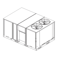
7½ Ton Downflow and Horizontal
General 5, 6¼, 7½ Ton
Data
Standard Efficiency
✲Indicates both downflow and horizontal units.
 Loading...


