Enkapsis & EnerSure Platform Installation Guide Rev07.2
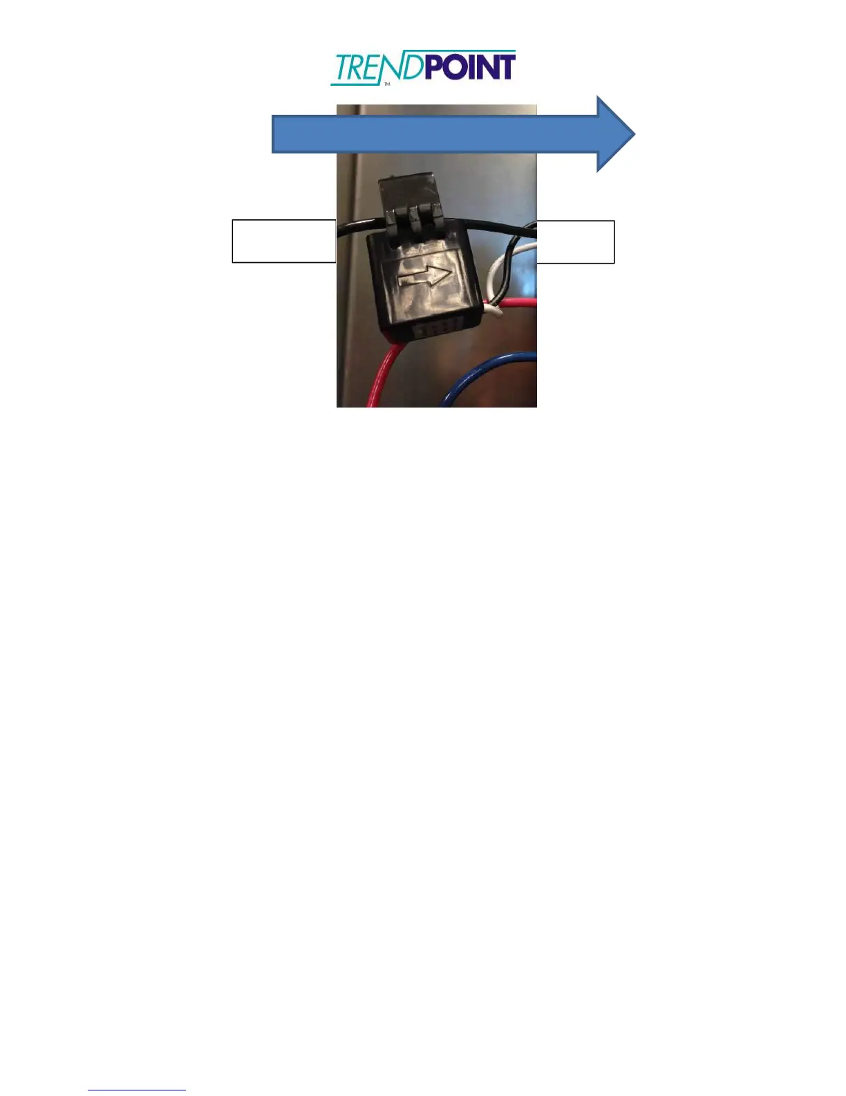
The CT’s may be simply hung on the wire which they snap around. However,
some customers may prefer to use Velcro strips on the bottom or hinged side of
the unit, to allow for ease of mounting and removal when necessary. Velcro is
non-conductive and should not bring any code issues into play.
The white and black lead wires from each CT are associated with specific ports
on the BCPM 2.0. Note that the numbered positions on your breaker panel will
correspond to the numbered positions on your BCPM 2.0 as follows:
Breaker Panel Circuit Number
BCPM 2.0 Connector Position
Each CT output has two wires. In North America, ALWAYS CONNECT THE
WHITE WIRE FROM EACH CT TO THE CONNECTOR PORT CLOSEST TO
THE RJ-45 CONNECTOR AND CONNECT THE BLACK WIRE TO THE
SECOND CT INPUT. ALSO, BE SURE TO KEEP THE PAIRED LEAD WIRES
TOGETHER. MIXING LEAD WIRES WILL RESULT IN LOSS OF DATA AND
POSSIBLE DAMAGE TO THE UNITS.
An example of connecting the CT’s would be connecting circuit number 1 on your
breaker panel to the bottom connector, terminal 1. Circuit number 23 is
connected to the second level connector, terminal 1. Circuit number 84 is
connected to the top connector, terminal 18. The odd numbered circuits on the
BCPM 2.0 are located on the left hand side of the board just as the odd
numbered circuits on the power panel are located on the left-hand side and even
numbers circuits located on the right hand side.