Enkapsis & EnerSure Platform Installation Guide Rev07.2
Current Transformer Installation
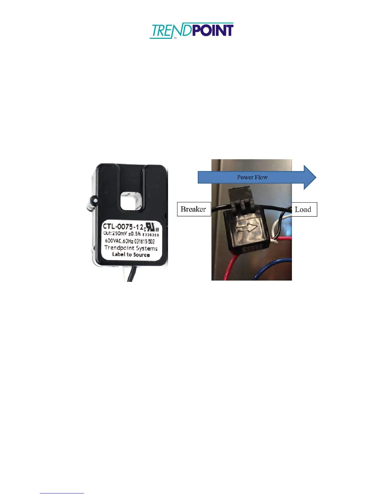
The standard CTs for the Bus2.0 system are 75 A split core CTs (Figure xx2.) The lead
lengths on the CTs can be cut to the desired length and the wires connected to the screw
terminals. The process of installation is as follows:
5.) Identify the arrow molded on the exterior of the CT or the label that says
“Label to Source”.
Figure 31: CT Orientation Marking
1.) Align the CT (Figure 31) such that the arrow is pointing in the direction of
power flow; pointing away from power source (circuit breaker) towards
load. If the CT does not have an arrow, it will have a label. The label
needs to face the power source.
Caution: Incorrectly aligned CTs may cause incorrect readings and
damage to equipment.
2.) Close the CT around the line being monitored. Ensure the CT is snapped
completely closed.
3.) Connect the CT to the corresponding circuit on the Bus 2.0 card.