Enkapsis & EnerSure Platform Installation Guide Rev07.2
EnerSure Bus
EnerSure Bus Overview
The Installation of the EnerSure bus system involves 3 separate components.
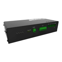
1.) Enkapsis PQM – This unit is mounted inside a Tap Can for the Busway system that
is being fitted with the EnerSure Bus product.
2.) EnerSure Bus Tap Cards - The Bus Tap Cards are mounted on each tap box and
connected in a “daisy-chain” format leading back to the Base Unit. Each Bus Tap
card can support a maximum of 4, or 8, CT’s.
3.) Current Transformers - The current transformers are placed inside of each tap box.
The CT’s are split-core type and are designed to easily snap around the feeds
providing power. The standard CT’s are 75A, but the system can support CT’s up
to 4000A.
*Note: This manual shows how to install and configure TrendPoint’s 4-Circuit Busway
product. TrendPoint also offers an 8-Circuit Busway product that installs and
configures in the same manner.