Enkapsis & EnerSure Platform Installation Guide Rev07.2
iBCPM2.0 PCBs
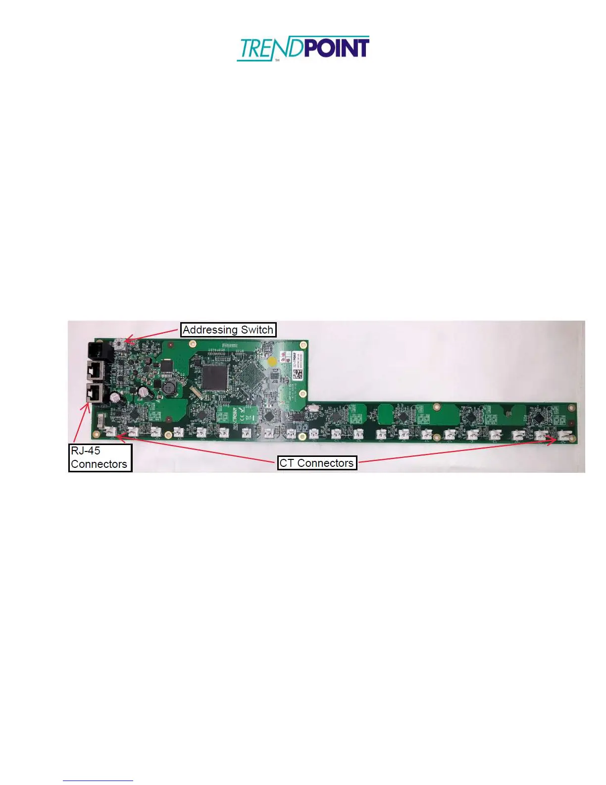
The iBCPM 2.0 PCBs (Figure 15) are designed to be mounted inside the panel being
monitored. The CTs provided with the system are equipped with 4” leads and an Amp
connector to be plugged into the IBCPM PCB PCB. The IBCPM PCB bracket has been
designed to mount next to the breakers inside the panel. However, mounting locations may
be changed to support the installation.
1.) Loosen the screws on the top and bottom of the panel as shown in Figure 16. Two
(2) screws are located on each side of the panel, totaling four (4) for a standard 42
circuit panel board.
2.) Place the iBCPM PCB mounting bracket under the screw heads and re-tighten the
screws.
Figure 15: iBCPM2.0 PCB
NOTE: The iBCPM 2.0 PCBs can be placed in a top-feed or bottom-feed panel. The
RJ-45 connectors can be on the top of the panel or on the bottom to facilitate the
installation. Designation of a top-feed or bottom-feed panel is performed during the
commissioning and setup of the system using the onboard web interface.