Enkapsis & EnerSure Platform Installation Guide Rev07.2
Current Transformers
Standard CTs for the iBCPM system are 75A split core CTs with a 3” lead fitted with a
crimp connector. The iBCPM system supports various CT sizes up to 4000A. CTs larger
than 75A are shipped with a screw terminal connector instead of the crimp style
connector that is fitted onto the 75A CT from TrendPoint. The lead lengths on larger CT
sizes can be cut to the desired length and the wires connected to the screw terminals (See
Enclosure Wiring Instructions).
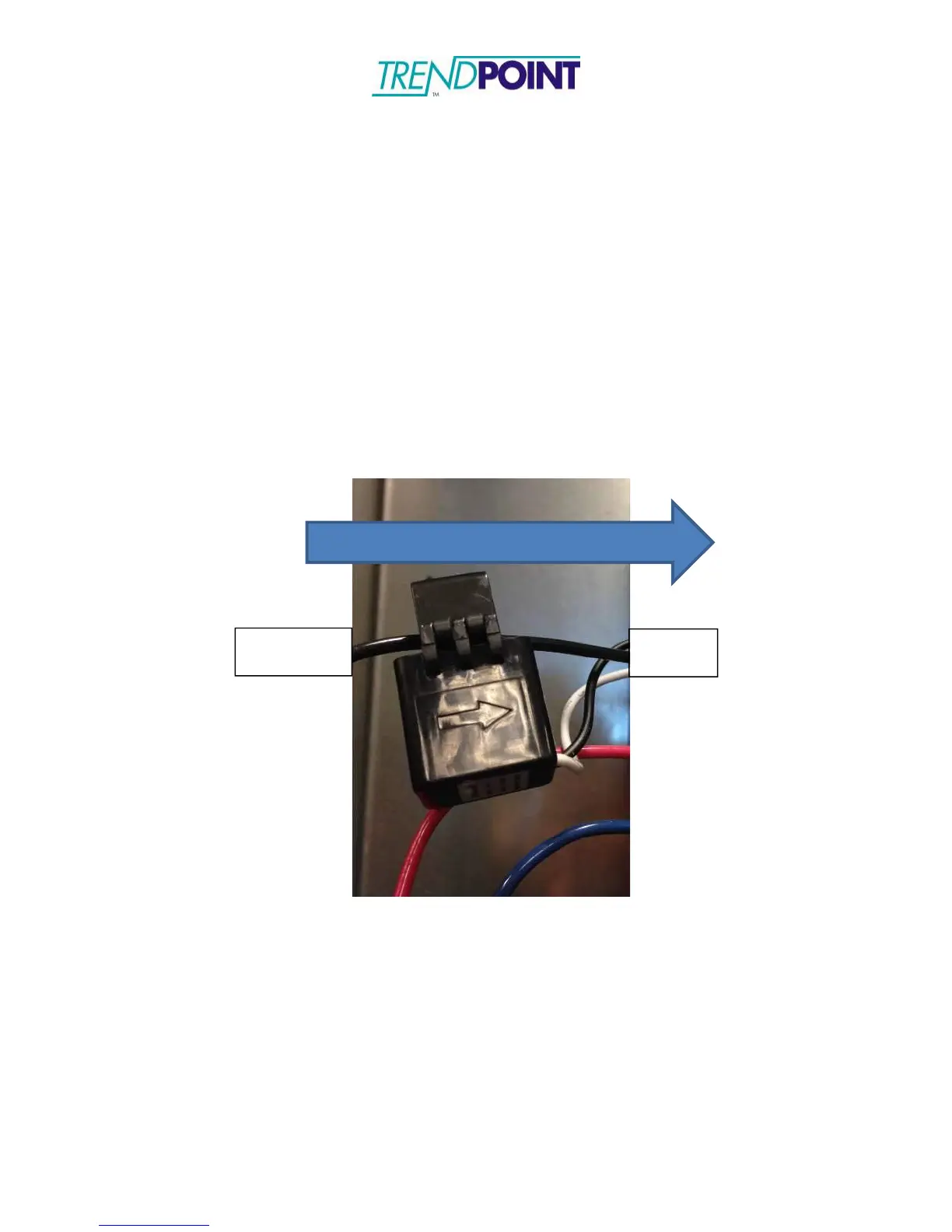
1.) Snap the CT around the line being monitored. Ensure the CT is snapped
completely closed.
a. Each CT is marked with an arrow. The arrow should point along the
direction of the current flow. (Away from the breaker)
2.) Connect the CT to the CT Strip channel corresponding to the circuit. The CT
Strip channels are aligned with each breaker.