10 Cables and Connectors
102 5700/5800 GPS Receiver User Guide
5700 Operation
10.1
Introduction
This chapter provides pinout information for the 5700 receiver
standard and optional cables. This information can be used to build
special cables for connecting the 5700 receiver to devices and
instruments not supported by the standard and optional cables.
10.2
Port 1, 2, and 3 Connectors
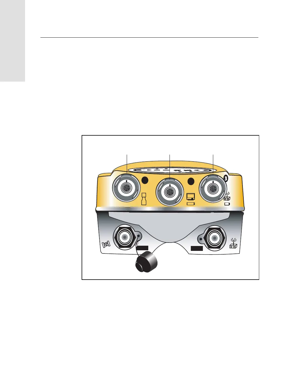
Figure 10.1 shows the location of the 5700 serial ports.
Figure 10.1 5700 serial ports
1
2
GPS
RADIO
Port 1 Port 2 Port 3