13 Setting up the Receiver
126 5700/5800 GPS Receiver User Guide
5800 Operation
13.1
Introduction
This chapter provides general information on setup, connection, and
cabling for the 5800 receiver.
13.2
Parts of the Receiver
All operating controls on the 5800 receiver are located on the front
panel. Serial ports and connectors are located on the bottom of the
unit.
132.1
Front panel
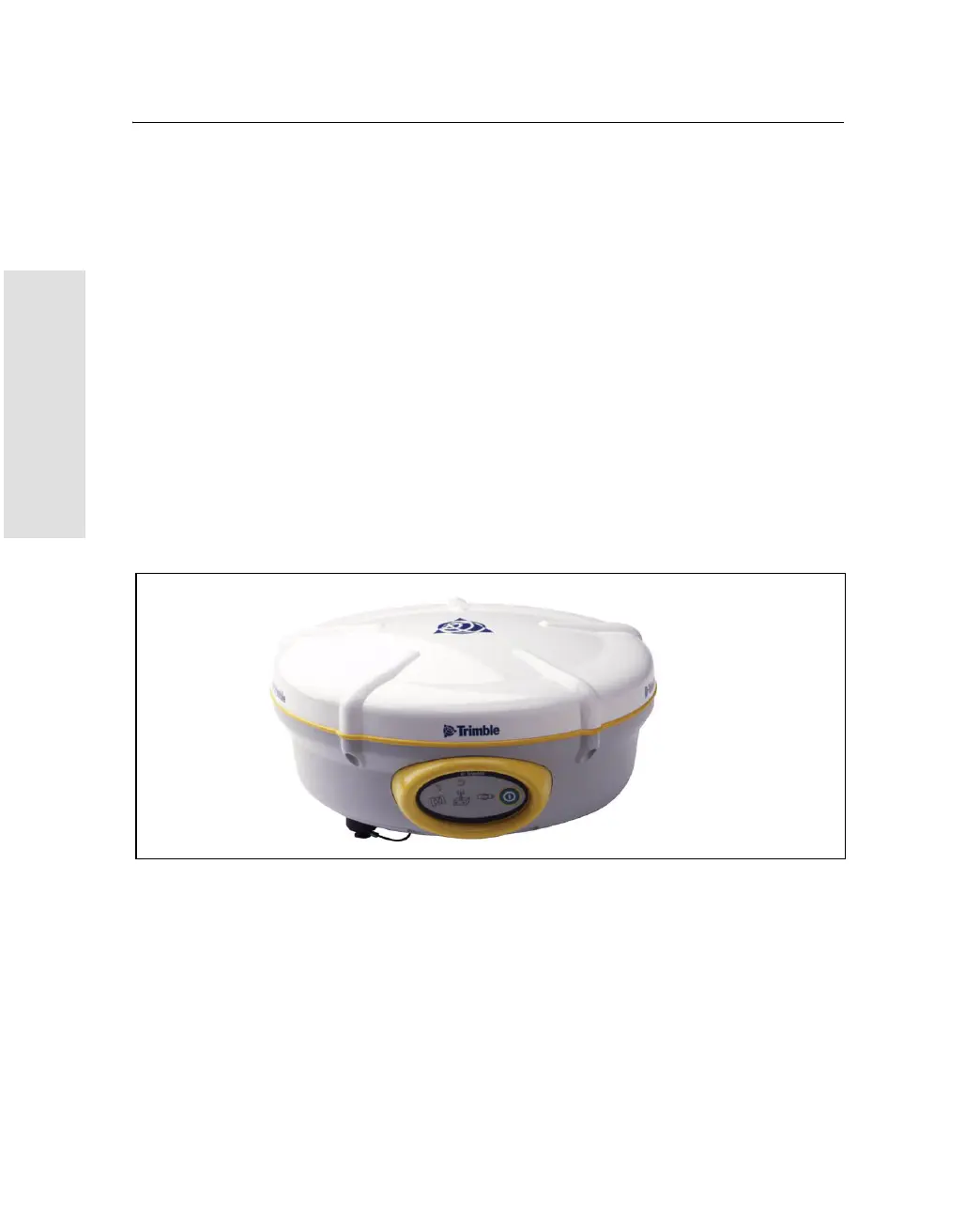
Figure 13.1 shows a front view of the 5800 receiver. The front panel
contains the three indicator LEDs, and the power button.
Figure 13.1 5800 receiver front panel
The power button controls the receiver’s power on or off functions.
The indicator LEDs show the status of power, satellite tracking, and
radio reception. For more information, see LED Behavior, page 137.