5700/5800 GPS Receiver User Guide 23
Setting up the Receiver 3
5700 Operation
32.1
Front panel
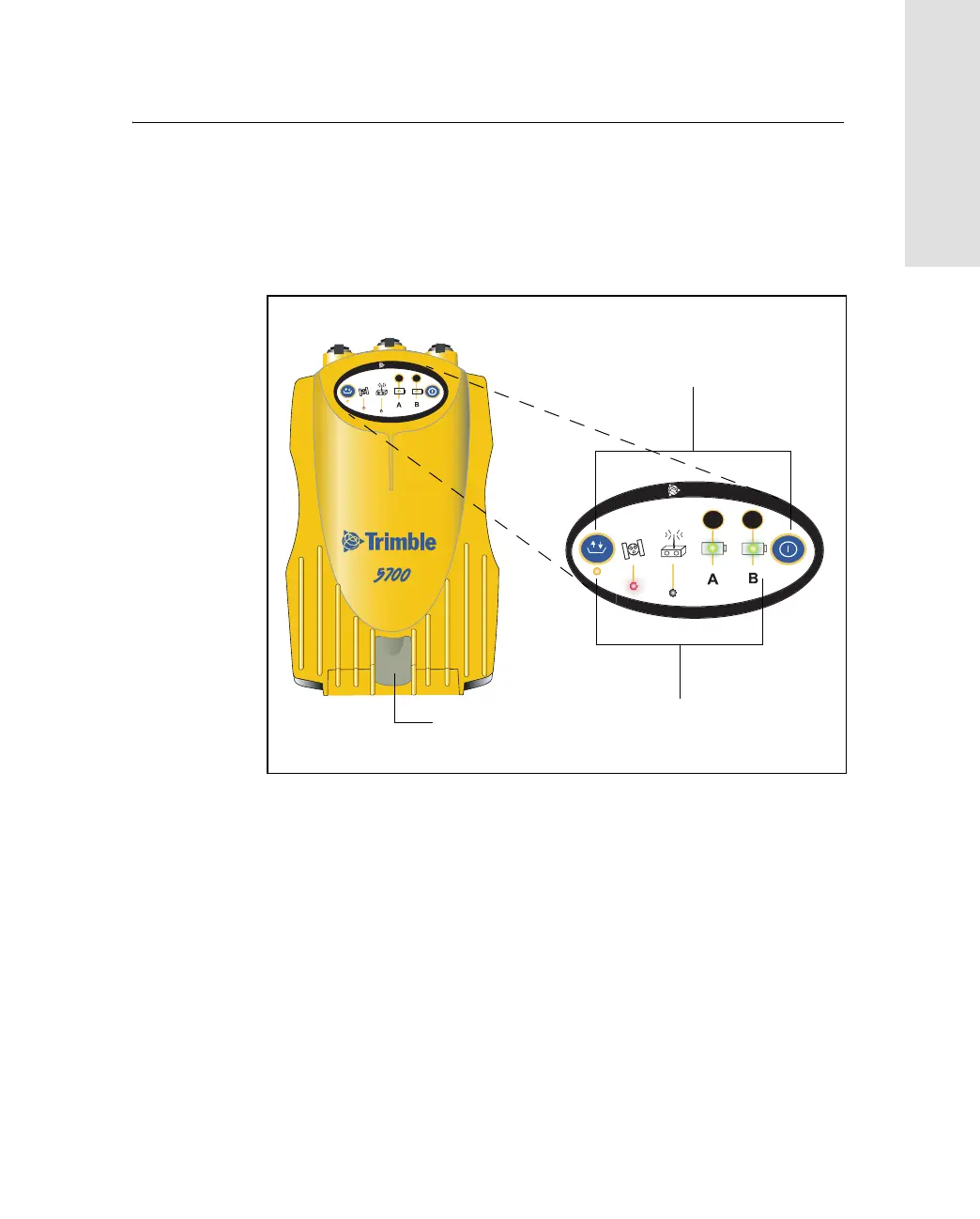
Figure 3.2 shows the front panel of the 5700 receiver. This panel
contains the five indicator LEDs, the two buttons, and the catch for the
CompactFlash/USB door.
Figure 3.2 Front panel
The two buttons control data logging, data management, power, and
settings. For more information, see Button Functions, page 48.
The indicator LEDs show the status of logging, power, satellite
tracking, and radio reception. For more information, see LED
Behavior, page 49.
USB door catch
2
3
t
2
3
t
Buttons
Indicator LEDs
CompactFlash/