-
9
-
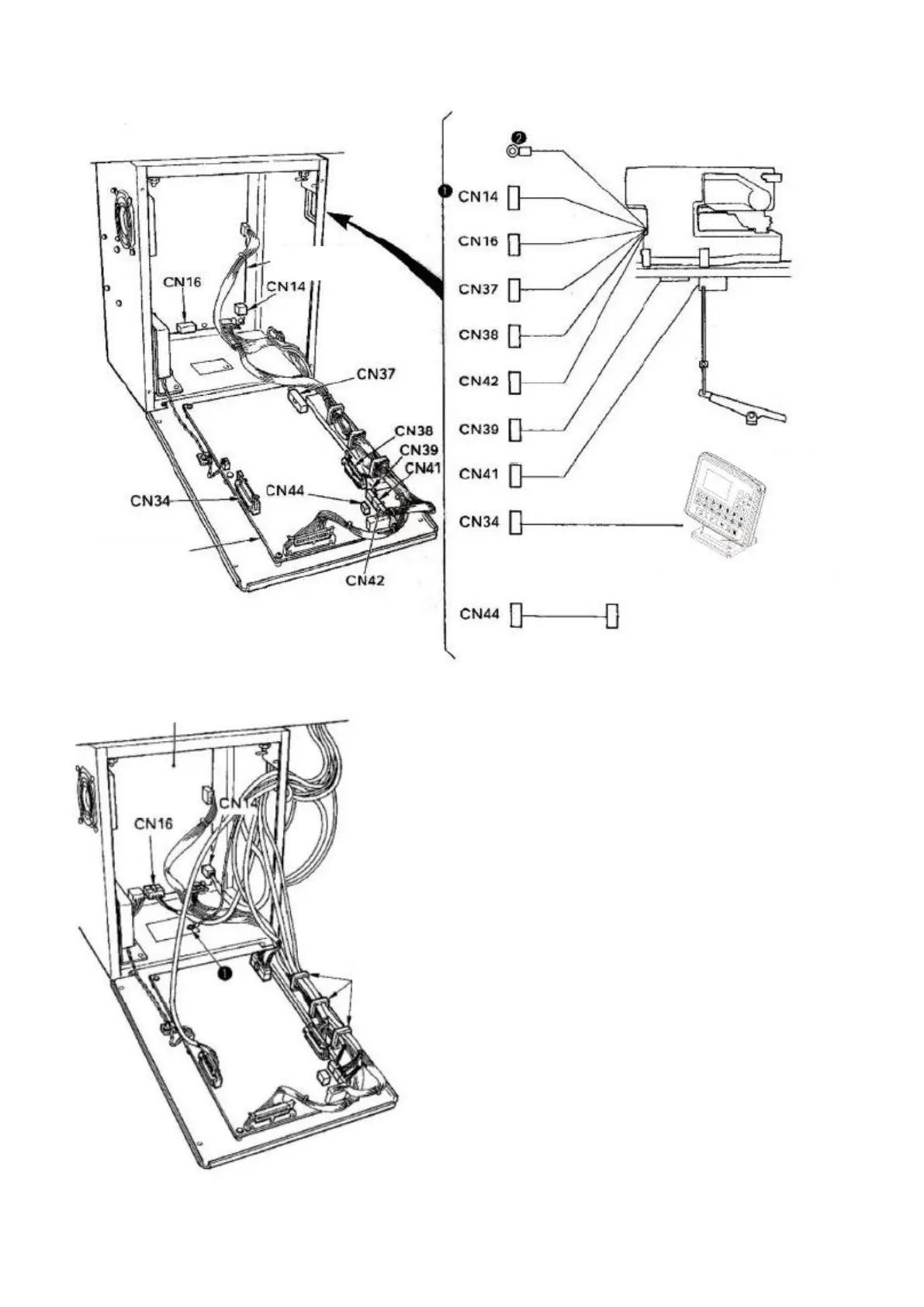
(8) Connection of the cable
1) As shown in the figure, pass 4 cables, which are on
the right part of cables connected to the MAIN
printed circuit board, through cable clamp A and
insert them to corresponding connectors (CN38, 39,
41, 42). Insert the cable connected to CN37 directly
to the connector without passing through cable
clamp A. In addition, when using electric bobbin
winding device (optional), please pass the cable
through the cable holder and then connect it to
CN44.
2) Directly insert the cable connected to the operation
panel on the left of MAIN printed circuit board to
CN34.
3) Directly insert cables connected to SDC printed
circuit board to CN14 and CN16.
4) Secure the ground wire with the setscrew
❶
.
Electric bobbin winding device
SDC printed circuit board