UniPOS IFS7002 two signal loops
Instruction Manual Page 26
Revision 11/01.17 Of 145
10. Disabled component
10.1. Description
The fire control panel enters Disabled component after a manual operation, disabling a specific
component – a fire alarm zone, addressable device or monitored output. The condition is handled via
Information and Control screens. A disabled zone is not monitored for activated fire detectors or fault
condition. A disabled addressable device is not activated (if it is an executive device) and is not
monitored for activation (if it is a fire detector) or fault condition. A disabled monitored output is
switched off (the executive device is not able to respond) and is not monitored for fault condition.
Where disabled zones, disabled addressable devices or disabled monitored outputs are available,
the LED indication illuminates and the relevant message is displayed
10.2. Indication
10.2.1. LED and sound indication
The condition is indicated by the Common indicator (Disabled component) illuminated in
continuous yellow light.
No sound signaling is supported for Disabled component condition.
10.2.2. Text messages
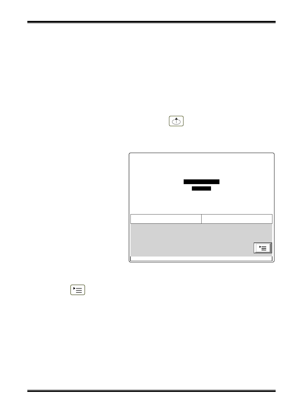
If a disabled component is
available, a table giving information
on the total number of disabled
devices and faults appears on the
LCD display. The second line of the
table’s left column displays the total
number of disabled components; the
second line of the table’s right
column – only the number of
disabled outputs (monitored outputs
and addressable output devices):
To display the text message for
each fault condition, enter
Information and Control Mode (see
section 12.2.2).
10.3. Using the keypad
For Disabled component condition 1 active button is supported. Where the fire control panel
operates in combination of other conditions, their buttons are active too.
Press button (Menu) to enter Information and Control Mode.
11. Test Mode
11.1. Description
The fire control panel enters Test Mode through manual operation setting a fire alarm zone to
Test Mode. The condition is handled via Information and Control Screens (see section 12.3.2).
Where a fire alarm zone is set to Test Mode, the following changes take effect:
Where Fire condition stage I or Fire condition stage II is detected in the zone, sound and
LEDs indications, associated addressable, controllable or relay outputs are not triggered; i.e.
the fire control panel does not enter Fire Condition;
Where Fault condition in a zone is registered, (i.e. fault in any device, integrated in the zone),
sound and LEDs indications or the relay output for fault condition are not triggered, i.e. the fire
control panel does not enter Fault Condition (with the exception of the isolator of a device in
the zone, because it would break the integrity of the loop; in this case a fault in the device
would be registered, but not fault in the zone);
FIRE CONTROL PANEL IFS7002
UniPOS
Thu 11 Feb 2010
11:48:24
Faults Total: 00000/00000*
Disables Total: 002
Failed Outputs: 00000
Disabled Outputs: 001
 Loading...