EasyManuals Logo

Uponor UponorControl System User Manual

Uponor UponorControl System
46 pages
To Next Page IconTo Next Page
To Previous Page IconTo Previous Page
Page #42 background imageLoading...
Page #42 background image
UPONOR CONTROL SYSTEM WIRED - INSTALLATION AND OPERATION MANUAL
42
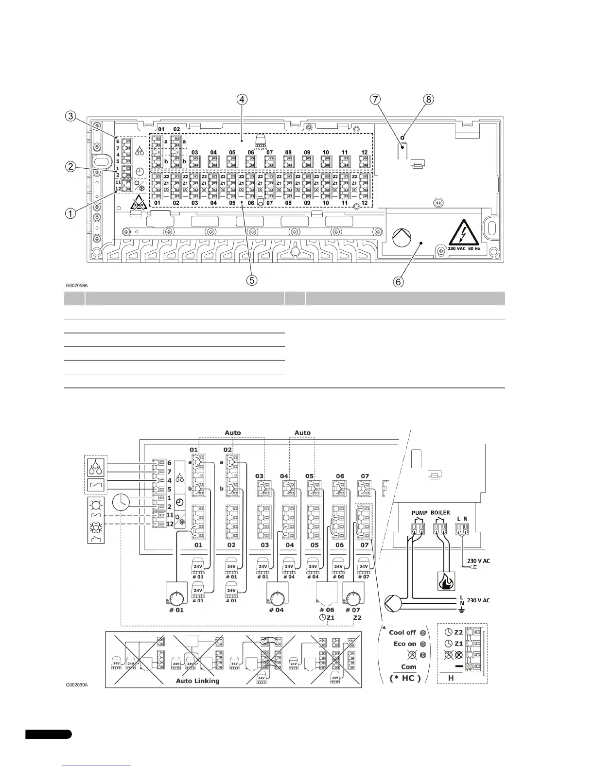
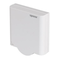
Uponor Controller C-35 layout
C-35 wiring diagram
Pos. Description Pos. Description
1 Connectors for heating–cooling relay 7 Push-button for Heating or Heating / Cooling mode
2 Connectors for timer 8 Bicoloured power indicator
• Red = Heating mode
• Green = Heating–cooling mode
• Off = Power off
3 Connectors for dew-point sensor unit
4 Connectors for 1–14 actuators
5 Connectors for 1–12 thermostats
6 230 V AC compartment

Table of Contents

Questions and Answers:

Question and Answer IconNeed help?

Do you have a question about the Uponor UponorControl System and is the answer not in the manual?

Uponor UponorControl System Specifications

General IconGeneral
BrandUponor
ModelUponorControl System
CategoryTemperature Controller
LanguageEnglish

Related product manuals