UPONOR CONTROL SYSTEM WIRED - INSTALLATION AND OPERATION MANUAL
43
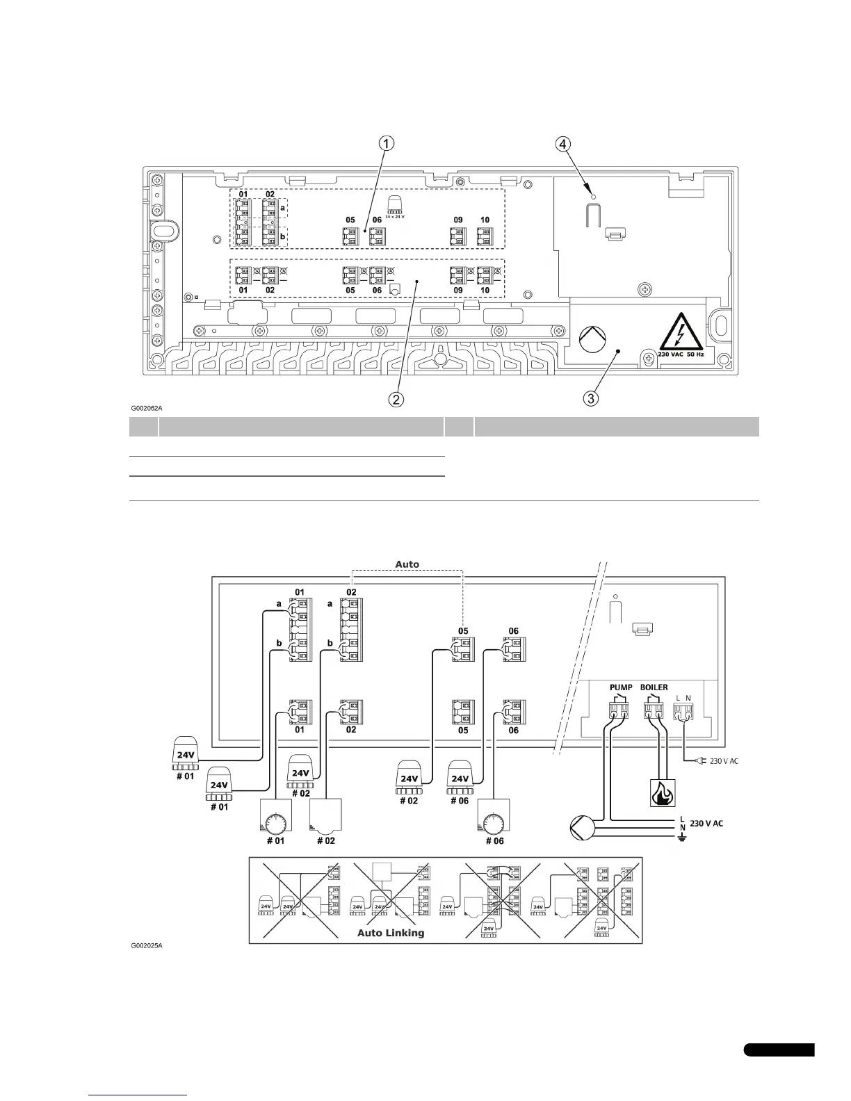
Uponor Controller C-33 layout
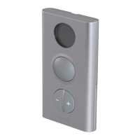
C-33 wiring diagram
Pos. Description Pos. Description
1 Connectors for 1–8 actuators 4 Power indicator
• Red = Power on (heating mode)
• Off = Power off
2 Connectors for 1–6 thermostats
3 230 V AC compartment