4. Individually remove each additional
cover or guard equipped with switch
and repeat steps 2 and 3. Make sure all
covers and guards are securely in place
after all switches have been tested.
5. Check pressure switch in oil mist lubri-
cator. Turn off air supply on lubricator.Turn
power disconnect switch “ON”and push the
“START” button. The machine should NOT
start. Only location 7 and the light corre-
sponding to the pressure switch in the lu-
bricator should be lit on control monitor. A
function check for oil supply necessitates
draining oil from lubricator and is therefore
omitted.
6. Push “STOP” button then disconnect
and lock out power source.
OPERATION
Safety Switches
29
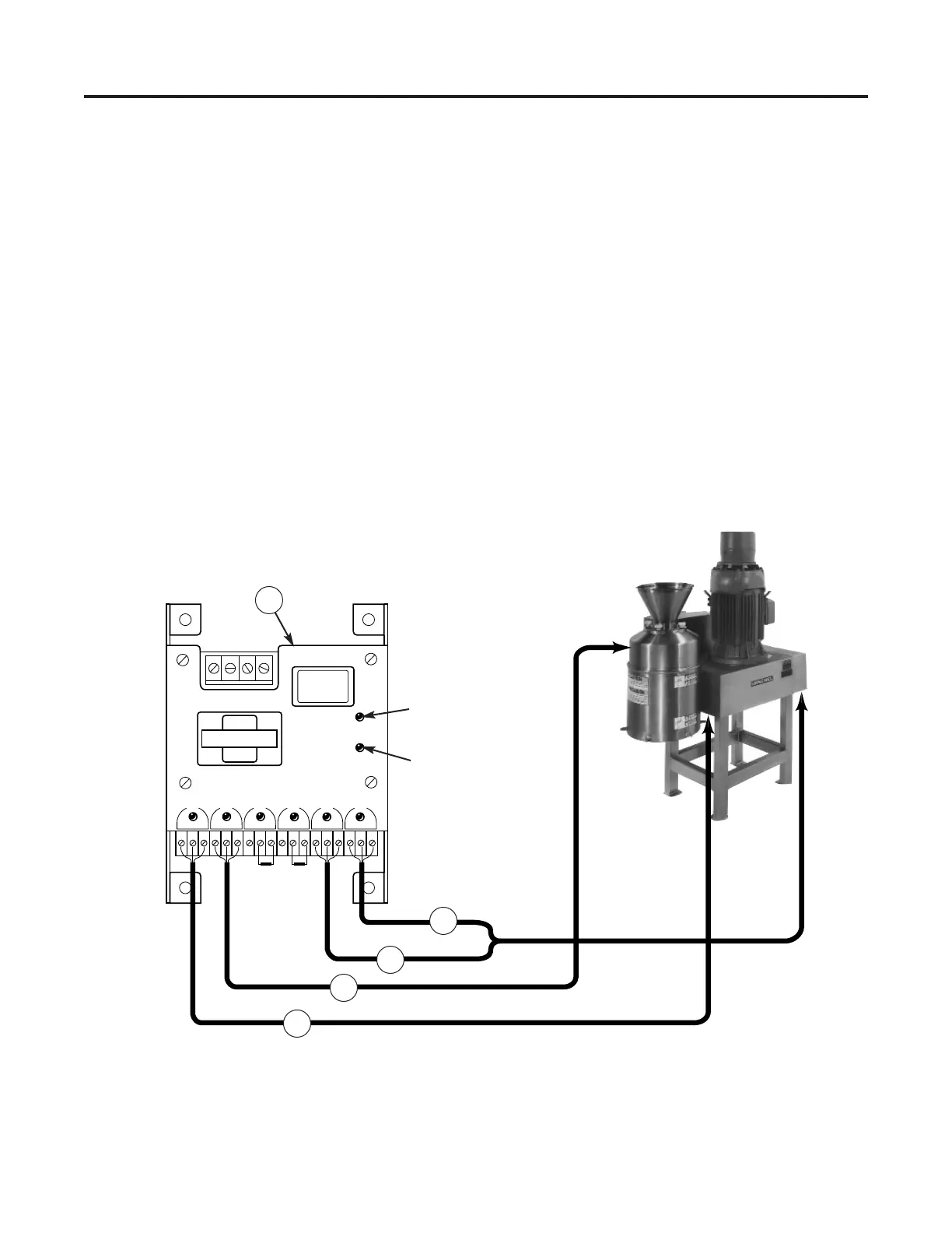
Figure 24 — Control monitor indicator lights with corresponding covers and guards (1) Belt Guard, (2) Upper Enclo-
sure, (3) Pressure Switch, (4) Low Oil Switch, (5) Control Monitor
 Loading...