INSPECTION
w
WARNING:
In the event of an electri-
cal problem, only a qualified electrician
should inspect or repair the fault. Always
disconnect and lock out power source be-
fore beginning electrical inspection or re-
pair.
The electrical assembly must be in good
working condition before operating this
machine. For a description of control monitor
and safety switch operation and method for
checking this system, see “Safety Switches”,
page 28. Electrical schematics are located on
pages 130–138. Refer to Figure 77 and
inspect the following items in the electrical
assembly:
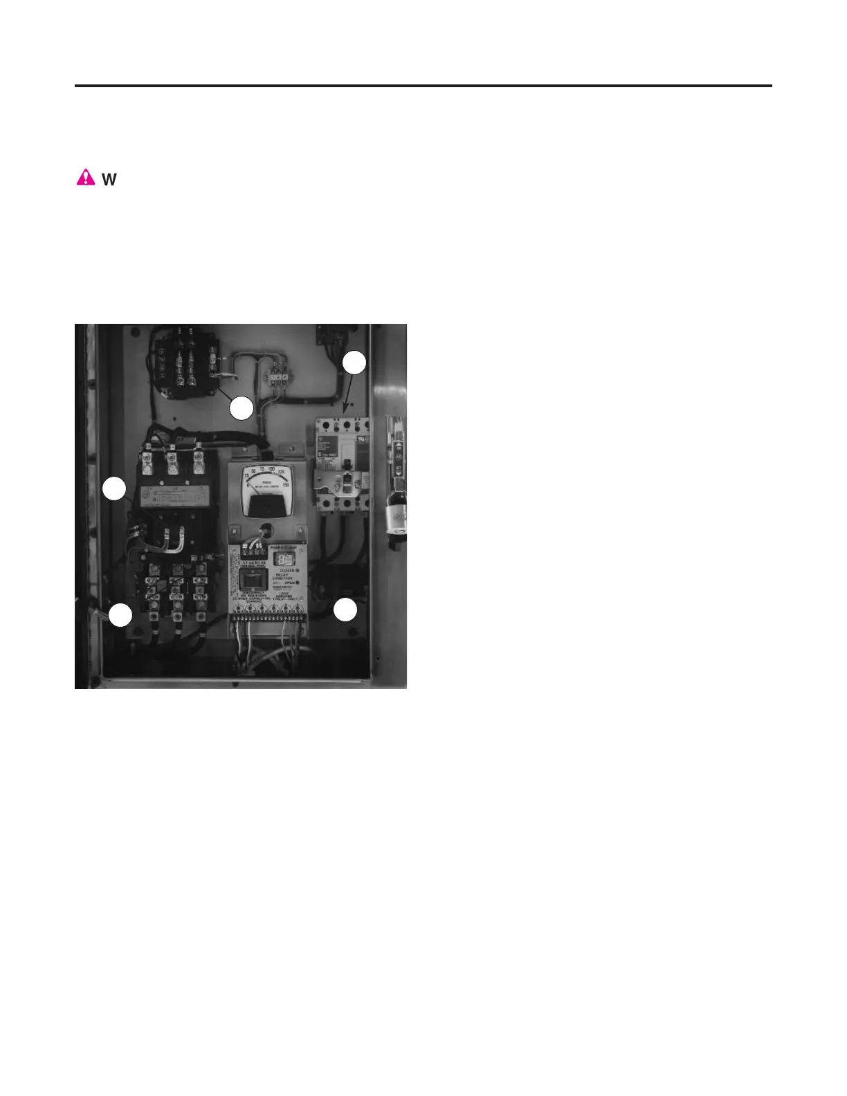
Starter enclosure: Inspect interior of
starter enclosure for moisture and corrosion.
Check gasket around door and window.
Breather drain should be free from obstruction.
Inspect stop and start push button assemblies
and pilot light assembly for damage or corro-
sion. Replace rubber boots and pilot light lens
if damaged.
Fuses: Remove transformer fuses. Check
with an ohmmeter or continuity light. If one
fuse is replaced, all others of that type fuse
should also be replaced. Remove and inspect
control monitor fuse (Figure 78, page 73).
Replace if necessary.
Heaters (thermal overloads): If heaters
have been tripped several times they may fail
to reset. If one heater fails, all heaters in that
starter should be replaced. Check for proper
motor current draw if heaters continue to trip.
Starter coil: Disconnect leads from coil at
front of motor starter and check with an ohm-
meter. Replace if necessary.
Safety switches: Check sensors, actua-
tors and cords for damage.
Switches should
be replaced if any defect or damage is detect-
ed.
Check switch alignment. Actuator must be
within 1/16" of sensor to complete safety
switch circuit.
MAINTENANCE
Electrical Assembly
72
Figure 77 — Typical starter enclosure interior. (1) Cir-
cuit Breaker, (2) Starter Coil, (3) Heaters, (4) Control
Monitor, (5) Transformer
1
2
5
3
4