OPERATING PRINCIPLE
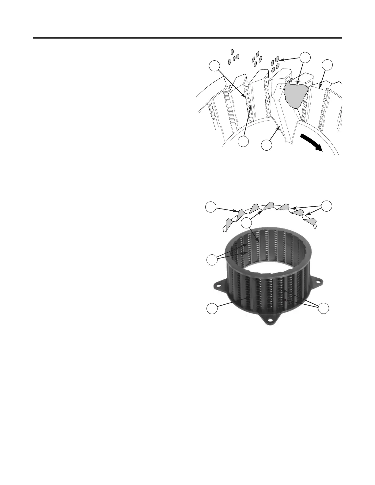
The impeller forces product against uniform-
ly spaced thin horizontal bars, or separators
(Figure 11). Small portions of product project-
ing into the spaces between the separators are
cut off into flakes by spaced columns of vertical
knives.These flakes fly outward and away from
the cutting head. The wall surfaces between
the vertical knives are relieved to eliminate rub-
bing friction that would produce heat. See
pages 112 thru 115 for a description and list of
cutting heads.
DESCRIPTION
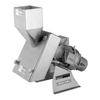
The cutting head is a ring of vertical knives
and horizontal separators in a rigid, one piece
unit (Figure 12).Cutting heads are identified by
the Urschel 5-digit part number and a corre-
sponding description number.The description
number indicates the height of the head (2 or
3"), the pattern and number of columns, the
openings between and thickness of horizontal
separators, and the material of construction.
See page 64 for more detailed information.
Cutting heads are available in two different
styles, each made by a different method:
Urschalloy cutting heads are cast from one of
the toughest and most wear resistant alloys
known; fabricated cutting heads are made of
individual pieces of a tough special alloy stain-
less steel, assembled and silver brazed to-
gether. Each style of cutting head is available in
several different types (Figure 13, page 19.)
The type indicates the pattern and number of
columns, which contain the cutting edges.
Fewer columns will produce a thicker particle.
OPERATION
General Information, Cutting Heads
18
Figure 11 — Cutting head operation (1) Horizontal Sep-
arators, (2) Vertical Knives, (3) Impeller, (4) Product, (5)
Relieved Surface
1
2
4
5
3
3
Figure 12 — Typical cutting head and cross section (“K”
type Urschalloy) (1) Columns, (2) Horizontal Separators,
(3) Openings Between Separators, (4) Vertical Knives
4
2
2
1
1